I've been working on a microphone...

  • Thread starter Thread starter crazydoc
  • Start date Start date
crazydoc

crazydoc

Master Baiter
and I decided I'd use my 1000th post here to show its progress (or lack thereof) so far.

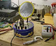
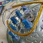
I thought I'd try to use a large diaphragm (in this case about 4 inches diameter) tuned subsonically, and try to pull off different harmonic content from different portions of the diaphragm, then mix them to the output.

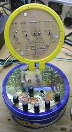
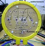
This particular prototype uses 5 reflective optical sensors, one positioned centrally and the other four at different radii from there. Their outputs are mixed and sent to a mic preamp.

Major problems are:
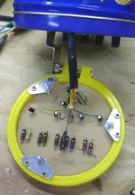
1) diaphragm material and tensioning it. I'm using aluminum leaf reputed to be 1 micron thick. This stuff tears if you look at it wrong, and being able to tension it evenly over a ring (in this case an embroidery hoop) has been futile. If I could get some mylar or other strong but thin material of the required size this problem would be solved.

2) The sensors (LED coupled to phototransistor), not being manufactured for audio purposes, are quite noisy at the required amplification. Maybe I'll contact a manufacturer and see if they can be made as a special order to have less noise.

The mic sounds like crap of course. Maybe there's a market for a sound like someone at the bottom of a well, buried under a bunch of snakes. I can call it the hisspit mic. :)

Anyway, back to the drawing board. Any suggestions appreciated.
 

Attachments

  • hissypit.webp
    hissypit.webp
    61.2 KB · Views: 474
First--you need to get rid on ALL wrinkles. You might also look at using an IR led's with IR detectors instead of photo transistors. If that doesn't work, a laser and laser detector unit could be used. Simply bounce the laser off the film. Similar methods are used for covert listening systems.
 
sloop said:
First--you need to get rid on ALL wrinkles.

First off that thing looks pretty sweet. As for the wrinkles, try something that has more adjustment than a single screw. Maybe an old rototom or something.
 
Doc,

My applauses! DIY seems never die!

Some thoughts about your design. From the picture it seems that it is a pressure-gradient design and you are absolutely correct--for a right frequency response it should be tuned at subsonic frequencies, so the whole system will be mass controlled. The easiest way to do it is to increase size of the diaphragm, but there are a few potential problems here.
1) Directivity pattern is not good in both, vertical and horisontal planes with diaphragm THAT big.
2) The big diaphragm is prone to uncontrolled resonances and diffractions.
3) Because of forces on a diaphragm in pressure-gradient system, the HF range will be seriously compromised here.

I am familiar with the leaf you are using, and don't think you will be able to get rid of shrinks. You have to find something Mylar based. Here are a few options:

http://www.2spi.com/catalog/crystals/mylar_film.shtml

Here you will need to find a way to make the diaphragm reflective. BTW, if you decide to get this material and don't need that much, I will join you and we can split cost.

2) Space blanket. It is quite thick for diaphragm use, though--about 1/2 mil, or 12um.

3) It seems that I found a source for 6um aluminum coated Mylar. Contact me through PM, if you are interested.

The biggest problem, however, is a low noise optocoupler. The guy, who started DIY optomic thread suggested one, as he claims very low noise (and quite expensive) device. I would have gone ahead and buy it to try, but it has an internal amplifier, which turns me off.

<The mic sounds like crap of course. Maybe there's a market for a sound like someone at the bottom of a well, buried under a bunch of snakes. I can call it the hisspit mic.>

At this point it doesn't matter--I think it is a good start, and please keep posting on the progress.
 
Fab! I don't understand more than about 30% of the words, but you have my respect sire :)
 
Marik said:
Doc,

From the picture it seems that it is a pressure-gradient design....QUOTE]

I thought "pressure gradient" implied that one end of the diaphram would have to be sealed off from the other, so that it would act like a barometer and move with slight changes in air pressure.

That thing looks awesome! Regardless of how well it works, it must have been a blast to build.
 
<I thought "pressure gradient" implied that one end of the diaphram would have to be sealed off from the other, so that it would act like a barometer and move with slight changes in air pressure.>

Noiseportrait,

By definition, pressure-gradient means that force actuating a diaphragm is the difference between front and rear sound pressures, so the back is open.

The "barometer" acting, when the back is sealed, is a 'pressure' system.
 
sloop said:
First--you need to get rid on ALL wrinkles.
I know - I consider it a partial success that the thing is intact, and at least relatively symmetrical.
You might also look at using an IR led's with IR detectors instead of photo transistors. If that doesn't work, a laser and laser detector unit could be used. Simply bounce the laser off the film. Similar methods are used for covert listening systems.
The device I am using is IR
http://www.fairchildsemi.com/pf/QR/QRE1113.GR.html
but is an integral LED emitter and phototransistor detector.
The reasons I chose it were size (3mm square by 1.5mm tall) so I could mount a number of them under the membrane) and cost (cheap).

Would a photodiode be as noisy?
I don't know anything about laser emitter/detectors - any useful links?

Thanks for your input.
 
mshilarious said:
First off that thing looks pretty sweet. As for the wrinkles, try something that has more adjustment than a single screw. Maybe an old rototom or something.
The way I envisioned adjusting it was merely pushing the smaller hoop through the larger one which would have the membrane lying on it. Push farther - more tension. When the material tears easily, this doesn't work at all. The one in the picture is actually glued onto the inner ring, out of frustration, so there is no way of altering the tension.
Thanks.
 
Marik said:
Some thoughts about your design. From the picture it seems that it is a pressure-gradient design...
Actually at the present it is not - the pc board actually blocks most of the back sound, but this can easily be remedied in the future.
You have to find something Mylar based. Here are a few options:

http://www.2spi.com/catalog/crystals/mylar_film.shtml

Here you will need to find a way to make the diaphragm reflective. BTW, if you decide to get this material and don't need that much, I will join you and we can split cost.

That sounds like an option. I'll take 10 feet and you can have the other 290 feet.:D
I'm a real cheapskate - so far I've spent well under $10 for this thing, and would hate to make a $40 investment!

Just kidding - it sounds like a viable option, though I'd rather the width were greater. I'll PM you about the other option for the 6um aluminized stuff. I was thinking of using capacitor film, but it's not made large enough.

Thanks for your useful input. I'll post some more pics of the mic.
 
noiseportrait said:
...it must have been a blast to build.
Absolutely! There's nothing in life like having an idea and then bringing it to fruition, even though the product of the idea is nowhere near as cool as the idea. Sort of like any creative endeavor I guess.
 
This shows the mic with membrane off. The black knobs are the pots for adjusting gain of each sensor. The middle one is the master gain.

The five small black dots horizontally across the face of the pc board are the emitter/sensors (Fairchild QRE1113).
 

Attachments

  • hisspit3.webp
    hisspit3.webp
    66.7 KB · Views: 366
A closeup of the pc board. I put the op amp on the this board from laziness- so I wouldn't have to make another board inside the can. :)
 

Attachments

  • hisspit2.webp
    hisspit2.webp
    69.2 KB · Views: 358
The back of the board with the non-surface mount components.

The metal triangles contain spring loaded screws to move the board closer or farther from the membrane, as an adjustment of the sensitivity of the sensors.
 

Attachments

  • hisspit4.webp
    hisspit4.webp
    53.2 KB · Views: 355
The pots and wires inside the can - not the neatest in the world, but hey, it's just a prototype.
 

Attachments

  • hisspit5.webp
    hisspit5.webp
    58.2 KB · Views: 353
Some comments and a STUPID question

I think it's awesome that you're building your own mic. I have thought about trying that for some time now, although I don't know half of what I should know to do so. Here comes the stupid question:

How hard was it to make/understand how to make?

I mean I understand the physical difficulties, i.e. stretching the diaphram, soldering in a small space, figuring out the layout, etc...But how dificult is it to grasp the concepts needed to construct a simple mic? I would greatly appreciate it if you could point me in the direction of a good site with some info on the topic or anything of the sort.

In any case, you're my hero and have inspired me to actually try to build one of my own. Oh and I love the cookie tin - adds just the right touch of class.
 
crazydoc said:
The way I envisioned adjusting it was merely pushing the smaller hoop through the larger one which would have the membrane lying on it. Push farther - more tension. When the material tears easily, this doesn't work at all. The one in the picture is actually glued onto the inner ring, out of frustration, so there is no way of altering the tension.
Thanks.

Oh I see. I wonder if Mylar, or some similar material, has heat shrink properties?
 
OneRoomStudios said:
In any case, you're my hero and have inspired me to actually try to build one of my own. Oh and I love the cookie tin - adds just the right touch of class.

I concur wholeheartedly. This thing rules. It reminds me of the mini-ITX remote controlled Hummer PC I built. I had to sell it for cash, but man that was cool. I gotta try this mic thing someday too.

Please keep us informed of technical improvements.
 
Great job Doc!

Please let us know what ideas you have and what is your next step.

mshilarious said:
I wonder if Mylar, or some similar material, has heat shrink properties?

Yes. I picked the method when I was building and servicing electrostatic speakers. Apply the Mylar on the hoops, trying to do it as even as it is possible. Then with a heat gun (or even holding it above a gas stove) heat up the Mylar. You will see how the shrinks will dissapear, leaving even and uniformely stretched surface. Similar process (using ovens) is used in capsule production before tensioning and called 'cold flow relaxation'.
 
Cool! neat stuff there Crazydoc. Now I see where you got the name:)
 
Back
Top