Help w/mini pushbuttons.

dogooder

Well-known member
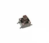
I have my Ensoniq ZR76 apart and need to replace switches. I bought ten. I don't see how to remove or replace them. The leads do not come through the boards.
I don't see how you would unsolder them and replace them. The only solution I see is to clip the leads at the front of the board and solder the new ones to them. I will include a picture of the switch, if anyone knows could you clue me in? They are listed as Pushbutton tact switch, surface mount, 7.3mm height.
Thank You.
 

Attachments

  • switch.jpg
    switch.jpg
    53.1 KB · Views: 3
Hi,
If you're unsure how to remove please do post a picture.
These are surface mount components so the four legs should just be set in solder on the board surface.
 
Here is a pic of one of the boards. How do you go about removing the switches?
Thanx
 

Attachments

  • board.jpg
    board.jpg
    127 KB · Views: 6
Yup - Just looks like normal surface mount, so the board has four pads per switch, the switch is set in place, then each leg is soldered to a pad.

For removal there's a few ways. For safety a lot of people would mask and use a heatgun, so all pads are soft simultaneously and there's little or not chance of lifting one by mistake.
I'm not that fancy so I do the soldering iron juggle. Heat a pair, switch to the other pair, repeat, until they're all soft enough that the switch lifts away (gently..don't prise).

If there's enough room to snip the legs without damaging the board then you can do than then heat each pad to remove what's left of the leg.
If that's feasible it's probably the easiest way.

For putting the new switch in it's easiest if you completely clean the four pads of all solder. Use a desoldering station or just some solder wick.
A short piece of woven cable shielding will do if you have neither.
Get your new switch in perfect position then solder one leg. Check position, with your housing if necessary, then solder up the other three.
It's much easier to move the switch and make adjustments if you've only soldered one leg. ;)
 
Thank you very much. I have never worked with these switches before. I only paid a hundred bucks for this keyboard with the intention of learning to work on it , so, wish me luck. This was either the right or wrong keyboard to start with. You have to work on it from the bottom, everything is upside down and you are fighting gravity. I had to remove the main board, and the keyboards action. This is my second time taking it apart, it only took me 40 minutes this time. I have a tool to suck up the solder and some solder wick. I think I can snip the legs. My QS8 is next, but that is just keys. Maybe I should find some cheap junk board on ebay with those type switches for a practice run. I tend to heat things up and don't have that steady of a hand.
 
Last edited:
No problem. Good luck with your project.
If you have any trouble feel free to post back here and I'm sure someone will help.
 
No problem. Good luck with your project.
If you have any trouble feel free to post back here and I'm sure someone will help.
Well, that didn't go so well. I replaced the switches, put her back together, fired her up, no LED display and little wisp of smoke? I shut it down immediately. Took her apart again and cant find anything wrong by eye? I saw which board the puff came from but cannot find any damage? Also, it seemed it came from a board I didn't work on? I took her apart once before, replaced the encoders and put her back together, no problems. I cannot have hooked up any ribbon cables wrong? I will pull the the toggles off the switches I soldered and take a look at them, none of them were on the board I saw the wisp come from. If I see no damage I am going to put it all back together again very carefully and fire her up again. IT'S A LEARNING PROJECT I keep telling myself.
 
N very B! Very often these switches are 'handed' that is to say their action is different depending on which way around they are fitted. (N/O can become N/C or v-v)
Check very carefully for an index spot or other mark.

Dave.
 
Hm, sorry to hear that.
Despite all the years of technological advancements, putting equipment on Mars etc, there's still no one who can put the magic smoke back inside for you. :P

Really, though, sorry to hear something went wrong.
Saying that, that's what a learning project is for so no harm done. If you can figure out exactly what happened then I'd consider that a win, long term.

Keep in mind it may have nothing at all to do with your switch - Some component could have made contact with chassis or some lead could have come loose.
As Dave says, orientation is usually important with those little switches.
With 4 legs (double pole, single throw?) if you were 180 degrees out there shouldn't be a problem but, depending on the circuit, 90 degrees out could cause problems.
If the board has traces going to all four legs then you could potentially be bridging two circuits which are never meant to meet. Definitely worth a check.
 
I am not sure what happened. I cleaned everything off, put her back together and now I have the display. I haven't gone further yet to see if anything I did is actually working. Will keep you posted. The only thing I can think of is one of the ribbon cables was not on correctly, either I was off one whole row or off two pins to the side off if you know what I mean? My eyesight at 69 years old ain't what it used to be. I have the ribbon cables labeled and they are all different so I know I didn't get the cables mixed up.
N very B! Very often these switches are 'handed' that is to say their action is different depending on which way around they are fitted. (N/O can become N/C or v-v)
Check very carefully for an index spot or other mark.

Dave.
A little late for that but I did go over the switches and could see no marking. The originals had a flat on the boss that the toggle goes on. These were square and symmetrical with no flat on the boss?
 
Your ribbon cable thing sounds likely.
For the switch orientation chances are you're correct, as the pairs of legs stick out at 180 degrees from each other.
It would be pretty difficult to put it 90 degrees out by mistake, but certainly worth mentioning.
 
I have all my voices and she is playing but now I have other problems I didn't have. Buttons that are now not working that did etc. I will take her apart again. I am getting pretty quick at it lol. I don't want to replace them all. There are 94 of them and that would cost me more than the keyboard did. I am a machinist. There is no way I put the switches in 90 degrees out, 180 possibly, but since I could see no markings on the switches for orientation I didn't take it into account. I may have to buy some more switches. I will look into the orientation issue. I threw out the ten switches I replaced.
 
Yes, I agree you could not get the switches 90dgrs out of whack but the ones I dealt with in a guitar pedal had a N/0 contact one side and a N/C contact the other. A prototype pedal came in for test and when powered up it was in the 'on' state instead of bypassed (the switches operated a flip-flop and then FETs) So you hoofed the pedal to turn the effect OFF!

IIRC the index was a tiny, sub mm pip on one corner?

Dave.
 
I will get around to taking her apart again and looking into the orientation issue. The switches are about a dollar a switch. If I put some in backwards and it didn't hurt anything I can probably unsolder them and orient them correctly, "I think.., therefore I am, I think." I will contact Syntaur where I bought the switches and ask them?
 
I only replaced nine switches and have one new one left over. On closer examination there are two tiny dots on one side of the switch. I am assuming that they
are for orientation purposes. Chance are half the switches are in backwards and with my luck it is probably more than 6 of them lol. There are no schematics available for this unit. Now I have to look at the original switches and see how they are oriented. Hopefully they are all oriented the same way, and I can determine their orientation and I won't have to guess? If this IS a learning experience I have learned a valuable lesson.
Thanx Guys
DW
 
On further recollections, I bought these switches off ebay, I bought the encoders etc. from Syntaur. I contacted the ebay seller and here was his
response. I thanked him but have my doubts, why two dots on the switch? He also doesn't realize he sent me contact switches and there are no "holes" in the board. I will wait to hear from Syntaur also.

"Good morning. There is actually no orientation to the tact switches but I know exactly what you are referring too. The best way to replace a tact switch IMO is to desolder and have all four pcb holes clear to stick the switch onto the board. It is totally an eye thing for the most part. The tact switch I then eye with an adjacent original one to see if it is correct . The main thing is that before soldering, it absolutely has to have the bottom of the yacht switch completely flat fit on all four corners of the pcb from the switch. This will make an even direct open front the switch when that according button is pushed. I generally push it in flat with one finger, and with my other hand, bend atleast two opposite corner prongs to hold it tight in place so that it doesnt move from once again being flat and in proper position. If you have your board still out, please send me a pic of the tact switches? Michael"
 
From the seller.

Ok I apologize as I didnt first remember what buyer you where as I thought we where dealing with an asr10 display as I sell alot of switches and alot of emails. Those are surface mount switches. I have never had to change a switch in an MR keyboard as of yet but I know that will happen: those switches are OEM and the same as an asrx uses. I would do this and maybe it would help. If you have an ohm meter and if there is just original one still intact on the board? Use your leads to have the tack switch to open or peg your meter on Rx1 on the top of the switch. Then, use that as a reference on the new switch with the replacement switch as the same as with your meter leads. As to commenting to Syntaur, I will leave that one alone. Michael​

 
From Syntaur,
Hi Jerry,


The switches can be oriented in either direction - if you spin them 180 degrees around, it won't matter.


If you are still having issues, it is likely that the switches themselves are not the problem. It could be trouble with the circuit board, or with a component on the board. If you have a multimeter or continuity tester, you can check on the circuit board itself whether the switch is working. It should show continuity (across opposing solder pins) when the switch is pressed. Testing this on the circuit board, rather than on the switch itself, will also verify that the solder connection is good - since these are surface-mount parts, they are more tricky to solder.


Sam Mims
Syntaur
 
Sounds like orientation isn't an issue.
That's good advice above.

The chances of multiple switches failing are pretty low - Testing, without removing from the board, should be very easy.
You need to be sure exactly what these switches are, first, but the chances are they are double pole, single throw, which would make orientation a non issue as long as the legs are pointed the right way.

Looking at the attached image, you can see it wouldn't matter if they're upside down or not,
if they are DP-ST.
 

Attachments

  • dpst.jpg
    dpst.jpg
    2.7 KB · Views: 0
Back
Top