Best 60$- MXL mic?

  • Thread starter Thread starter Vagodeoz
  • Start date Start date

Which one to buy?

  • V63M

    Votes: 17 25.4%
  • 990

    Votes: 16 23.9%
  • Cube

    Votes: 1 1.5%
  • 909

    Votes: 3 4.5%
  • Another one below 60$ (specify plz)

    Votes: 4 6.0%
  • Keep your 60$

    Votes: 26 38.8%

  • Total voters
    67
Vagodeoz

Vagodeoz

One-Man-Band
Hi guys, since a friend is making an order , I thought I might get something too. I have about 60$ to spare right now and I was thinking about getting a mike. I have heard some good stuff about MXL and I thought it was the time to give them a chance.
Here are the options I found:
V63M
MXL 990
Cube
909

Or any other suggestion of another brand? (it must be in musiciansfriend)
 
if u feel u must buy one try an mxl 2001

that one was said to be ok and sells for cheap now.

otherwise id save your money

there are some mxl v67g's going on ebay for $80 at the moment though if ure interested.
 
Thanks! but they must be bought from musiciansfriend :(
And they aren't selling the 2001.
The only MXL options in budget sold in musiciansfriend are the ones posted earlier. :(
 
Well, seeing so many people voting "keep your cash" I think I won't buy one... yet. I will wait until I have more money to get a better one. Instead I will get an 8 channel snake for now.
Tnx for voting.:)
 
I have the 990/991 double pack kit thing. The 990 pretty much sucks butt, it's boxy and funky, but the 991 isn't half bad for the money. Works out to about the magic $60 you're looking to spend. It's a tad bit bright and not the most detailed on the planet, but I've successfully used it for drums, acoustics, guitar cabs, bass cabs, vocals and horns and made some pretty decent recordings.
 
I voted to keep your money. I got the 990/991 pack for $50 or $70 when it was on sale at GC (can't remember - $70, I think). I've sort of destroyed the 991 by modding it so much with my low skills, but it still works OK - I would probably use it some if I didn't have other mics that work better for the stuff I would use it for.

I did replace the capsule coupler cap in the 990 with a polystyrene ( 30 cent upgrade, if you don't count the tool cost) and it's actually not too bad after that. It was horrible before that.
 
I did replace the capsule coupler cap in the 990 with a polystyrene ( 30 cent upgrade, if you don't count the tool cost) and it's actually not too bad after that. It was horrible before that.

can you expand on this?

i "lucked" into a pair of 990's with shockmounts etc for $50 a while back (in quotes because i am not sure how lucky i actually was). at first, i was impressed with their sound for the $$$, but now i mostly do not use them for anything. there is just something "not right" about their sound. not sure if "boxy" is the right adjective, but i feel pretty good about "unnatural". i have other mics to use, and almost always do. i have, however, used them as a stereo pair in a 2-mic live recording, and it actually came out pretty decent (all things considered).

a
 
i "lucked" into a pair of 990's with shockmounts etc for $50 a while back (in quotes because i am not sure how lucky i actually was). at first, i was impressed with their sound for the $$$, but now i mostly do not use them for anything. there is just something "not right" about their sound. not sure if "boxy" is the right adjective, but i feel pretty good about "unnatural". i have other mics to use, and almost always do. i have, however, used them as a stereo pair in a 2-mic live recording, and it actually came out pretty decent (all things considered).

Try the capacitor swap. A lot of Chinese mics open right up by replacing the coupling cap.


Step 1: Size the capacitor.

You need a capacitor with the same value---usually measured in µF (microFarads) or pF (picoFafards). It must have at least the same voltage rating. It's okay to use one with a larger voltage... with the caveat that larger voltages result in larger capacitors, so if there are space constraints, you should keep that in mind.


Step 2: Order the capacitor.

Wait two weeks. :D


Step 3: Make sure the new capacitor will fit where the old one is.

If not, additional work may be needed. :D


Step 4: Remove the old capacitor.

Take solder wick and place it alongside the contact. The edge of the wick should touch the solder at the base of the contact. Heat the contact until the solder melts. Once liquid, the solder should easily flow onto the wick. If it doesn't, adjust the position of the wick until it does. You should end up with a clean contact with no solder on it. The capacitor's leads should freely wiggle in their holes. The cap should then pull out easily. If not, you may need to repeat this step and/or head one or both leads while you pull, but hopefully it will "just work".


Step 5: Clean the holes.

Use a needle or straight pin to clean out the holes if they show any obstruction. Always push the needle/pin through from the trace side so you don't lift the trace accidentally. Also, don't ever push it in so far that it would widen the hole or you'll lift the trace.... :)


Step 6: Repair the trace you broke in step 5. :D :D :D

If this happens, it's not a big deal. A little cyanoacrylate adhesive (super glue) should fasten the trace back down. Try to keep it off the top of the pad as much as possible. Warning: if you do this, solder outside. Cyanoacrylate fumes are nasty stuff. :D

If the trace tears, get a circuit writer pen and use that to draw a new trace. Make sure you get a nice heavy flow that is relatively thick and at least as wide as the original trace. Let it dry several hours before doing anything further.


Step 7: Install the new component

Push the leads gently through the thru-holes (vias). If they snag, don't push. Repeat step 5. Bend the leads as needed to make this work. If the original cap is a radial capacitor (vertical), you may want to bend the leads and mount the new capacitor in a similar orientation to make it fit. Make sure it will not hit the top of the case before you solder or trim anything!


Step 8: Trim the leads

The leads on the new components should stick up about 3/16" (5mm) above the board, give or take. Use your judgment---make them about the same height above the board as the original leads were.


Step 9: Solder the new component in place

Heat the contacts and touch them with the solder. The solder should flow and cover the contact and the pad on the board. Heat until it flows across both contacts, then remove the heat. Be careful not to move the contacts after you remove the heat. The resulting solder should be shiny. If it looks dull, it probably moved during cooling. Reheat. If this happens too often, your room may be too cold---are you soldering in sub-zero temperatures? You don't want the solder to cool too quickly.... :D


Step 10: Test the mic

If everything worked, the mic should sound much better.
 
Last edited:
i will consult the google, but if you can link to further info on this i would be obliged.

a
 
i will consult the google, but if you can link to further info on this i would be obliged.

I added some. The key is choosing the right part. You either want polystyrene or other film (foil) capacitors. You specifically want to avoid anything ceramic, electrolytic, and oil-and-paper. The first two should be avoided because they sound bad. The third, while apparently a good choice from a sound quality perspective when new, has a short life expectancy due to absorbing water from the air.
 
what dgatwood said, except that it's slightly easier, because the capacitor I'm talking about is on the backside of the circuit board, and it's up on two posts. It's the only capacitor in this situation, so it's hard to miss.

The polystyrene or polypropylene capacitors usually look like little clear plastic cylinders with a smaller metallic looking cylinder encased inside, with two stiff wire leads coming out - either on each end of the cylinder or both off one end.

I can't do a before/after pic, but I can do an after pic - give me a few hours to set up and distract those who would prevent the project :D
 
OK - here are some pictures:

caps.jpg


here are three different types of 1000pf caps -- I've had good luck with the one in the upper right, OK luck with the one in the upper left, and the one at the bottom didn't work for me (I've had good luck with these in different values in other positions in the mic, but not here -- it tended to "saturate" and distort a lot, and I tried a bunch of different specimens in a bunch of different mics, all with the same result)

caps1.jpg


ooh! [adverse conditions.... That's my 17 month old daughter, helping out]


installed.jpg


here it is installed -- I tried to draw a really lame arrow pointing to where it is.

So, yes, I totally know what you're talking about - it was "boxy", which to me, was like the mic or the source (but not both) were inside a carboard box, and with this change, it's much better. The 990 has a nice chew-proof grill, too.

I just grabbed the old one and heated up those terminals, and pulled it off, then gently positioned the cap above (pre-trimming the leads) on those posts, and heated them up until it stuck there. Not the best technique, since it's better to clean off the existing solder, or you risk getting hissy noise because the connection is bad. Took me a couple of tries, but I got a clean connection after a while.

I replaced some other caps on the other side of the circuit board, but didn't notice so much of a change -- the most bang for the buck (30 cents) is with this one.

Note that on this board in particular, you'll see posts from folks like dgatwood, who actually know what they're doing, and others from users like me, who don't know what we're doing (but are slowly learning but will probably never completely catch up) and are kind of swept up in the whole thing with usually positive results -- keep that in mind :D
 
Note that on this board in particular, you'll see posts from folks like dgatwood, who actually know what they're doing, and others from users like me, who don't know what we're doing (but are slowly learning but will probably never completely catch up) and are kind of swept up in the whole thing with usually positive results -- keep that in mind :D

I wouldn't say I know what I'm doing. I have a pretty good idea, but the folks who know precisely what they're doing... that would be folks like MsHilarious and Marik.
 
heh, well thanks to the both of you. as it stands, i dont have a lot to lose, but apparently a lot to gain.

antichef, i went ahead and unscrewed one of the mic bodies to look at it--- completely different than the pics you posted. all components on mine are mounted on the other side of the board--- i.e. facing the jack. i would take a pic, but ALL of the batteries are dead--- i will post one tomorrow. to be sure though, the cap in question is located across the leads to the capsule, right? that is going to be a bear to get to--- i will have to look at it tomorrow after the beer goggles are off.

thanks again, and sorry to derail the thread.

a
 
oil-and-paper. The first two should be avoided because they sound bad. The third, while apparently a good choice from a sound quality perspective when new, has a short life expectancy due to absorbing water from the air.

That actually takes a lot longer than you think, and newer PIO caps last even longer. I have no quams about PIO caps with the exeption that they are very large by comparison.
 
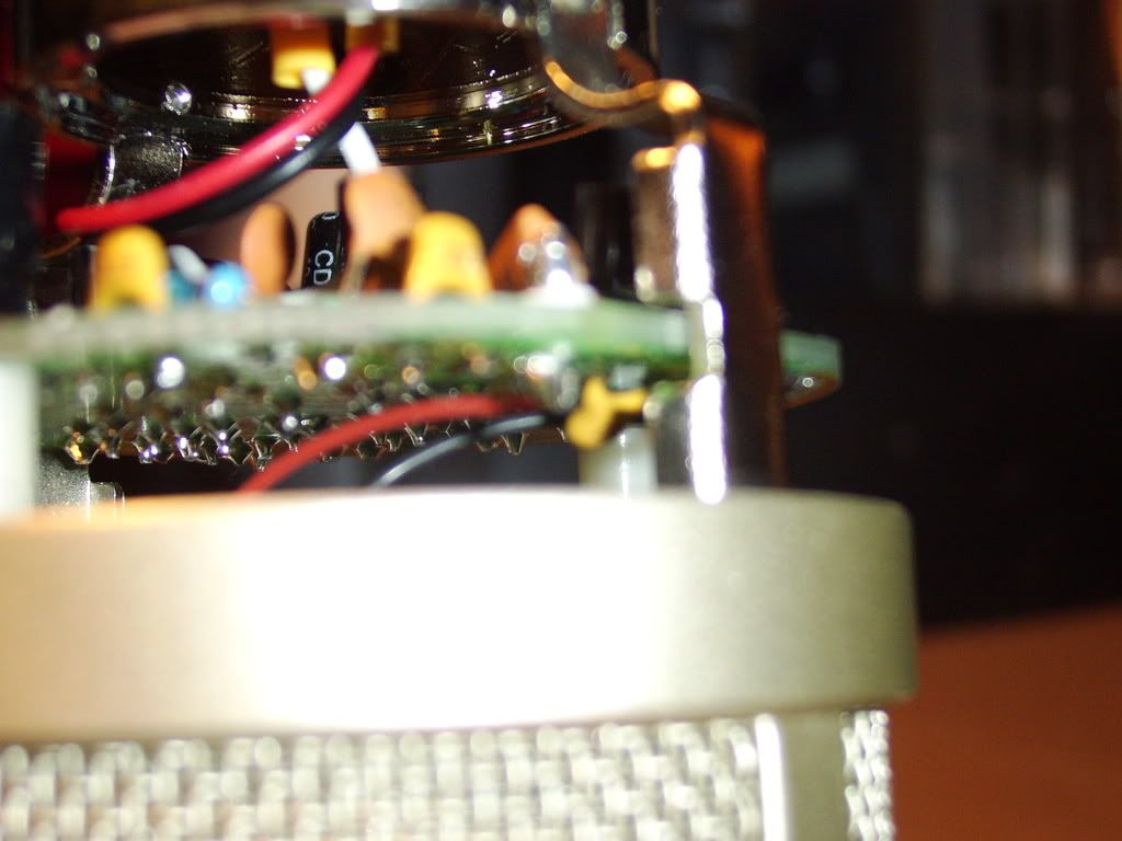
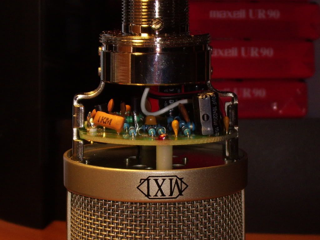
pics as promised.
the coupling cap is that itty bitty one on the "top" of the board that straddles the leads to the element. correct? is there a trick to getting these disassembled without wrecking anything? sorry for the blurriness--- my crappy SAMSUNG digicam sux at macro. i wouldnt recommend buying a SAMSUNG camera, but i digress.
STA73665.jpg

STA73661.jpg

a
 
yes - that itty bitty yellow-ish one that's in front and all blurry on the top of the board (which is on bottom in your picture, since the mic is inverted).

It's really not that difficult to disassemble, just unscrew the screws in those posts - no real risk.
 
Back
Top