TyphoidHippo
1Trillion K Platinum User
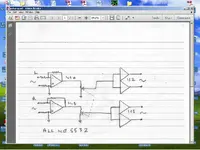
I'm trying to get up to speed with all this stuff, and I think I understand that if I wire a "quad potentiometer" inline between a balanced, stereo, line level source and an amp that it will work as a simple level controller.
Something like this: Slide Quad Potentiometer Alps 10K Lin 60mm Travel Qty 2 | eBay (and maybe wire it to some TRS or XLR ins and outs if I feel fancy when I'm actually doing this). Will this actually work? Seems like surely there's got to be some reason I can't have a 9 dollar solution to 2 broken mixing boards (which I was only using as level controllers) on my hands... Thanks for any input, guys")
Something like this: Slide Quad Potentiometer Alps 10K Lin 60mm Travel Qty 2 | eBay (and maybe wire it to some TRS or XLR ins and outs if I feel fancy when I'm actually doing this). Will this actually work? Seems like surely there's got to be some reason I can't have a 9 dollar solution to 2 broken mixing boards (which I was only using as level controllers) on my hands... Thanks for any input, guys