Let's do a basic noise/gain analysis. An ideal mic preamp has noise of -133dBV, which is the thermal noise of a 150 ohm resistor. Not too many preamps hit that, but many come within 6dB. So if the purpose of this amp is a mic preamp, we have to be really concerned with input noise.
You will almost never see a pot at the front end of a mic preamp for that reason, and if you do it will be more like 1K. A 100K pot, worst case scenario, has thermal noise of a 25K resistor, which is -111dBV. That will only be OK for condenser mics, and relatively hot ones at that.
I don't remember the noise of 6418, but I think it's probably in the -110 to -120dBV range. I will try to test that, but let's say it is -110dBV. That noise will sum with your input noise, so you'd have -108dBV, and be multiplied by the gain of the circuit. If you have a gain of 8, now your noise is -96dBV. But the noise of a 500K resistor is also -98dBV, those will sum to -94dBV. A nominal mic signal of -40dBV/Pa is now -28dBV, with signal to noise ratio of only 66dB.
One way to solve that problem is to put your 1:4 transformer at the front, that gives you 12dB of gain, and in a perfect world, your equivalent input noise would drop to -118dBV, which is workable.
They designed this thing as a headphone amp, so they could get away with not really caring about noise, because they are presuming feeding it a 0dBV signal. 6418 isn't going to cope very well with that after a gain of 8, but according to them that is "tube sound".
I'm afraid there is no solution for their topology that will fix the noise problem without reducing gain of the circuit, which makes the noise problem worse, which requires you to further reduce gain . . .
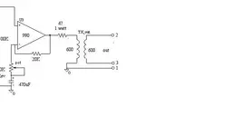
A functional mic preamp with 6418 has a 1:4 transformer input (invert the signal at the transformer), followed by 6418, followed by a FET (or noninverting opamp), then a pot (or put the pot in the opamp's feedback loop), maybe another 6418 if you don't use the opamp, then finally some type of output buffer, probably a noninverting opamp. Another transformer on the output if you wish. That could have reasonably low noise, a pleasant amount of THD, and any amount of total gain you require. It could be fully discrete if you want, and all tube & FET if that floats your boat. You could have two pots for a topology like a Fender Champ if you want to drive a 6418 deep into overdrive.


")
