Somnium7
Noise Criminal
PSU Completed
I hate this power supply! I never want to see the inside of it again")
It is working now ...and better than it ever did before I might add.
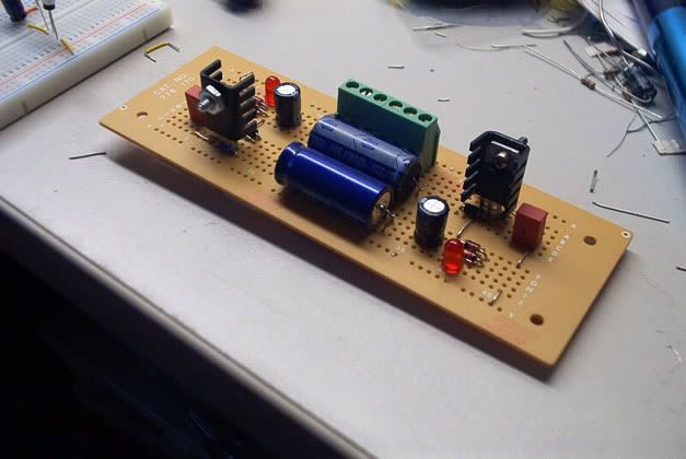
Check out the new regulator core PCB
See the album for the entire story...
http://s108.photobucket.com/albums/n13/somnium7/gear/PSU/?albumview=grid
I still need to perform a few tests and take some measurements. Everything seems alright though. I can't wait to get back onto the audio stuff again!
I hate this power supply! I never want to see the inside of it again
It is working now ...and better than it ever did before I might add.
Check out the new regulator core PCB
See the album for the entire story...
http://s108.photobucket.com/albums/n13/somnium7/gear/PSU/?albumview=grid
I still need to perform a few tests and take some measurements. Everything seems alright though. I can't wait to get back onto the audio stuff again!

 I don't know, Doc... I don't think any of us have ever thought of solder fumes before.
 ")


 . The second time around I was planing everything ahead, used computer to draw layout, then printed it out and followed the 'blueprint'.
 :rolleyes:")