tascam M312B repair notes

  • Thread starter Thread starter evm1024
  • Start date Start date
evm1024

evm1024

New member
OK So I got the M312B on the bench and was checking it out. There are a few problems. Channel 8 and 12 were dead, you could see that the summing buss PCB had been cracked and repaired and the meter bridge had been pushed on in the past.

I pulled the meter bridge off ( using a 90 degree phillips head screwdriver and unmounting the meters) and took to it with a Ballpeen hammer on a vice. The side that is normally under the plastic end caps had been distorted due to the force. A few smacks and a few bends with a crescent wrench and it was good enough. Looks OK now.

The summing pcb as I said had been repaired before. I'm looking for one should you have a parts machine sitting around. It works and I'll leave it as it is. It failed because sometime inthe past there was a blow to the center of the bottem pannels. It bent the cross brace and cracked the summing PCB. I straightened the brace and will be adding screws and mounting plates on each side. Who knows where the originals are.

Now to the real gem of this post, the channel cards. What I discovered is that I have 2 versions of the channel strips. One has metal mounting fingers on the connectors. The other does not have these fingers. Both channel 8 and 12 are the ones without the fingers and both failed.

After some testing (I could get the card to work by moving it around) I discovered that the pan pot had broken solder joints on both boards. So I just touched them up with a little solder to reflow them. They are way in there but I was able to get to them using some caution without taking out the strip.

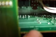
Here is an out of focus photo that shows the pan pot for channel 7 near the center and the pins of channel 8s pan pot just under it. There are 6 pins.

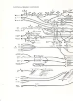
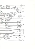
I could use any info, block diagrams, schematics, manuals for this that you care to share.

Regards, Ethan
 

Attachments

  • DCP_6258a.webp
    DCP_6258a.webp
    6.8 KB · Views: 142
Here is a photo of it on the bench

One reason to start this thread is to document what appears to be a "common" failure. Perhaps it will save someone a few hours of debug time. I've got about 4 or 5 hours into cleaning it up and getting all the channels working.
 

Attachments

  • DCP_6256a.webp
    DCP_6256a.webp
    37.4 KB · Views: 198
I have the full original manual for the M312B.

I could scan a couple of pages and post jpegs in pretty high detail but I can't do this until next week and I would need to know very specifically what pages you truly need to see.

Has TASCAM's parts department run out of copies of the manual at this point?

Good luck with the restoration project! It sound like your unit saw some pretty abusive road duty! :eek:

Cheers! :)
 
Monday

Thanks Ghost, I plan on checking with Tascam on Monday. What I could use is the block diagram right now. I think that you have scanned that in the past and PMed someone with it. If it is still around that would get me going.

It is not beat up at all really. I'll add a photo of the top some time soon. Then to make some wood panels for the sides. The originals are dog eared as one would expect. The question becomes teak, mahogany or bubinga or oak. Choices.

Ethan
 
Don't know if these will help or not... can't remember where I got them. :)
 

Attachments

  • 312Bflow1.webp
    312Bflow1.webp
    42.3 KB · Views: 110
  • 312Bflow2.webp
    312Bflow2.webp
    32.8 KB · Views: 89
And the manual costs.....

..... $50 plus $4 shipping from tascam. I bit the vullit and bought one. Due in this week.

I've reflowed a few more connections and it all appears to be working fine. It has been fun reading through all the prior posts (Ghost is quite helpful) and figuring out how it routes. The manual will be very good to have.

But I can't wait for the manual to arrive. I have to know. What does the BNC near the power switch do?

regards, Ethan
 
evm1024 said:
But I can't wait for the manual to arrive. I have to know. What does the BNC near the power switch do?

Talk-back mic.

EDIT:

Never mind... you said BNC. That would be for a light. The talk-back is below that.
 
Beck said:
Talk-back mic.

EDIT:

Never mind... you said BNC. That would be for a light. The talk-back is below that.

Yes, a lamp sounds right. I did measure 6 volt ac on it. And using a BNC makes sure that nothing else is plugged into it....

Thanks! Now I can rest easy.
 
evm1024 said:
Yes, a lamp sounds right. I did measure 6 volt ac on it. And using a BNC makes sure that nothing else is plugged into it....

Thanks! Now I can rest easy.
Littlelite makes bayonet mount lights that work with that mount available in standard and halogen...I've got one mounted on mine. ;)

Look for the G series products.

http://www.littlite.com/index.php

Cheers! :)
 
Bal out

The next problem to fix was a non functioning balanced stereo out. I traced this to a bad NE5532 opamp. Was it shorted or was something it did not like plugged into it no one will ever know. In any case it is an easy fix. Just remove the 3 screws holding the balanced amp board in place and position the board so that the solder can be sucked away.

I don't have any NE5532 so I replaced both the Left and right channels opamps with a Burr Brown (TI) OPA2227. I know that it is really hard to beat the NE5532 in a circuit that was designed for it. The OPA2227 looks very good and to my (constantly ringing ears) sounds fine. It is also a bipolar opamp with low noise specs and a few good DIY reviews.
 
an on to talkback

One more interesting problem. The talkback circuit does not work correctly.... Other signs are that there is a slight radio station pickup on the monitor/phones outputs. When PFL is activated the radio becomes louder and varies with the solo gain.


I'm speculating that the problem is in LC4966 fet switch (U405) on the monitor PCB. I've ordered a few of these and will report back if replacing it solves the problem and (it is hoped) gets rid of the radio pickup.

I'm posting about this now because I think I recall someone else getting radio but don't remember what the solution was.

I'll be pulling the monitor PCB when the parts get in and will also do a good visual inspection in case it is a grounding issue.
 
Effects return

OK new question just to verify that I'm not missing anything.

I put a line level signal into the effects return (1 or 2) and adjust the level to read comfortable on the meters. It reads on both L/R meters. Changing the pan does not move it from one output to another but it does move it from one master fader to the other. Very strange.

From what I can see on the schematic the effects return fader should put the signal on the stereo left or right bus and the headphone out and meters should not be "mono".

So what could be wrong....

Side note I still have a slight pickup of a radio station that may be due to grounding issues. Suggestions there?

Regards
 
Have you looked at any of the circuitry that controls the mono buss and mono master fader?

Perhaps something is amiss in there causing the RF and non desired mono effects you're experiencing?

Cheers! :)
 
Panic mode off

Thanks ghost,

Turns out to be a non problem. I just could not understand how effects return could be mono...and of course it cannot (when panned full l or r). So I went back to basics and discovered that tape in was also mono.

It appears that when touching up a cold solder joint on the stereo bus that the solder wicked under the silk screen.

regards
 
Back
Top