I agree with much of this ^^^^^.
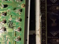
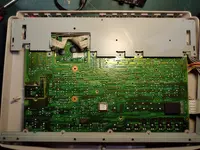
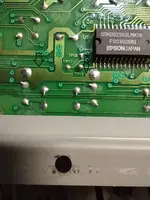
I don’t see contacts at all four corners. I see a joint to ground at the top of each switch that goes to the metal body, and then two contacts. If there were four contacts this would be a double-pole single-throw switch (DPST), but they look like single-pole single-throw to me (SPST), and the schematic confirms this. These are called “tactile” switches. You can search for them at Mouser or Digikey…other places as well. They are very common and you should be able to find replacements, but because there are literally thousands of different kinds, you have to have your “ducks in a row” as far as the specifics of yours. We know they are “through-hole” parts (they mount to the PCB through the board rather than mounting to the surface), they are SPST OFF-ON momentary switches, they are horizontally mounted, they are not lighted…but you also need to know the width and depth of the body of the switch, how high the top of the switch body is from the PCB, how far out the actuator protrudes, the shape of tip of actuator (concave, flat, etc…), and also the distance between the contact pins that are soldered to the PCB. Do you have a dial caliper? This is the best way to get accurate measurements of all these things. If you don’t have a dial caliper they are not expensive…you can get one from someplace like Harbor Freight online. Once you have all this information it might be easiest, rather than sifting through the thousands online, to just call Mouser or Digikey and ask for help identifying a compatible switch…Or open a chat with a sales rep. You would just start the conversation by saying you need help finding replacement SPST horizontal-mount through-hole tactile switches. If this seems complicated this truly is just how it goes when trying to keep older electronics gear going. The good news is you can still get these parts.
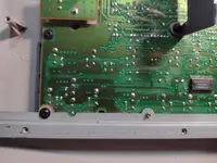
As far as spraying contact cleaner, if I’m understanding correctly, your efforts so far have been limited to jetting cleaner through the gap around the plastic buttons on exterior of the 788? If so, that is a useless effort. Like @Slouching Raymond is saying, the cleaner has to be jetted directly into the switch by any means you can…probably where the actuator goes into the switch body. You jet, exercise the switch (press it rapidly 25 or 50 times) and jet again to flush. Let it dry overnight, exercise again and try it out. It looks like what you’ve done so far just made a mess all over the PCB. Very important question: what contact cleaner are you using? Brand and type please.
Also, what is going on with capacitor C5? There is a group of four axial capacitors in a row, C4~C7 near a couple of the switches…does C5 appear damaged or is there just crud on it? The picture is too blurry when I zoom in but something doesn’t look right there.
So you can try properly treating the switches with an appropriate contact cleaner first as described above, but before you do anything I’d like to know what cleaner you are using. My hunch is that in the end the solution is going to be new switches.