snake cable through walls

  • Thread starter Thread starter mncheetah
  • Start date Start date
M

mncheetah

New member
I have XLR and TRS wall plates in my live room. After running the cable from these wall plates into the control room, what is the best way to fasten the cable coming through the wall of the control room. I do not want to use more wall plates, I would like to take the cable and have it come through the drywall about a 6" off of the ground, and directly attatch that to my mixer \ equipment, but I dont want it to look like crappy. So would I use an electric junction box, some kind of ring fastener, etc.... How is this typically done?

Thanks in advance.
 
mncheetah said:
I have XLR and TRS wall plates in my live room. After running the cable from these wall plates into the control room, what is the best way to fasten the cable coming through the wall of the control room. I do not want to use more wall plates, I would like to take the cable and have it come through the drywall about a 6" off of the ground, and directly attatch that to my mixer \ equipment, but I dont want it to look like crappy. So would I use an electric junction box, some kind of ring fastener, etc.... How is this typically done?

Thanks in advance.

I have seen electric boxes used for this purposes, but the best I have seen were handmade wooden boxes used as a junction station.
 
I had the same issues with the power feeds into my studio - power from behind the wall into the studio to a small 60A breaker box mounted on the side wall near where the feed came in. The wall the breaker box is on is accessable to humans, but the cable couldn't be run in that wall because its an ouside wall and there is a 6" diameter iron vent pipe in it that I certainly didn't want to drill into :)

So, I used ordinary conduit available from an electrical supply store or Home Depot (or Lowes) and ran the power cable in there.

For my vocal booth, I had similar issues because its "built" and not part of the house, so I yanked hard and managed to run a 24 TRS snake through 1.5" conduit and terminated it nicely in the vocal booth. Eight of the TRS terminates to XLR as well as balanced 1/4" jacks (in parallel) for versitility, and the remaining 16 balanced pairs are wired as (8) MIDI, (1) RS422, (1) RS232 and six unsoldered spares or future expansion types left hanging.

While RS422 and RS232 is normally not used in a vocal booth, it does allow me at some point to sling my Akai autolocator into the vocal booth for self-recorded guitar playing. Highly unlikely, but doable if I need down the road. XLRs and 1/4" are of quantity eight, because then I can stick a whole keyboard setup in the booth if I need to. Same for the eight midi connections - for the same imaginary synths. Overkill, yes, but at least I'll never outgrow it :)

Anyway, to summarize my answer, use electrical conduit. It protects the cables very well and provides some RMI shielding as well. Make sure you ground the conduit seperately from the audio cable :)
 
frederic said:

While RS422 and RS232 is normally not used in a vocal booth, it does allow me at some point to sling my Akai autolocator into the vocal booth for self-recorded guitar playing. Highly unlikely, but doable if I need down the road. XLRs and 1/4" are of quantity eight, because then I can stick a whole keyboard setup in the booth if I need to. Same for the eight midi connections - for the same imaginary synths. Overkill, yes, but at least I'll never outgrow it :)

Wow. Now THAT is thinking of the future.
 
version2 said:


Wow. Now THAT is thinking of the future.

Well, I will admit part of it is because I had spare snake cable to run, so it made sense to run it rather than 8 seperate mic cables. Mogami is good stuff :)

Part of it is having had a bedroom studio prior to this for five years, and running many, many cables out of the bedroom, down the stairs, into the living room, that I felt its better not to have to do stuff like that anymore.

Easy way to break one's neck :)
 
Well, thanks for getting me thinking. I am going to look at more possiblities in my routing scheme.
 
no problem.

If you find it difficult to bend steel conduit (or hire someone to do it for you - its a $100 tool actually) you can use PVC tubing. You lose the shielding of course from the steel conduit, but you gain ease of workability. Fit and glue, no special tools other than a hacksaw.

However, you are stuck with using elbows, which make the bends tighter.

The key to doing this is to lay down the PVC, snake the cable through the first straight piece, then through the elbow, then through the next straight piece. THEN glue it all together. If you glue it all together before snaking, its going to be quite tough to get the cable through, unless the PVC tubing is grossly oversized.

My 24CH snake was 1.25" diameter, and really didn't like being bent much.
 
So how does the conduit attatch to the wall? How far into the wall does the conduit have to go? how far out? Does a junction box fit into this? Sorry for sounding stupid, but I'm having trouble picturing how this would work. Could you draw me up a quick picture or something?

Thanks.
 
mncheetah said:
So how does the conduit attatch to the wall? How far into the wall does the conduit have to go? how far out? Does a junction box fit into this? Sorry for sounding stupid, but I'm having trouble picturing how this would work. Could you draw me up a quick picture or something?

Thanks.

No worries about the questions... text makes it hard to picture, I agree.

Unfortunately I'm about to leave NJ for my twice a month trip to Boston for the remainder of the week so I can't do a drawing right now, maybe when I get there. But in leu of some text, here is what I did in more detail.

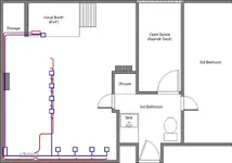
Here is my floor layout:
http://members.aol.com/midimonkey732/images/floorplan.gif

At the top of the picture, you see the vocal booth "over" the stair well.

Immediately to the left, is an area called "storage", which has a slanted ceiling, almost to the floor. The vocal booth does not have a slanted ceiling, its weird, but try to picture it.

On the inside of the wall thats against the Tascam TMD1000's area, on the inside, are two junction boxes. The lowest junction box to the floor is the one for power, which has four ordinary 3-prong outlets installed. The conduit comes out of the box and goes through the wall into the "storage area" immediately to the left along the floor, bends by the leftmost wall of the room, then down the diagram to the leftmost corner, where my 60A breaker box is located in the corner. All inside steel conduit.

For the audio, I basically did the same thing, except I used a 4-gang junction box at about waist high from the floor in the vocal booth, ran the conduit through the same wall into the storage area all the way to the leftmost wall, then at waist high, all the way to the bottom left corner like above, just 3' higher than the electrical conduit. Because the storage area ceiling slants so steeply, the power conduit is on the floor pretty much, and the audio/midi/digital signal snake is at the ceiling of this area, even though its only about 36-38" high. Leaves the storage area open enough I can toss junk in it. Right now its a mouse hotel, but thats another story.

If you really need a drawing, I'll be glad to do it sometime this week, and of course, answer anymore questions you might have. I believe I still have the wiring diagram for my entire studio on this laptop, so once I dock in boston I can make my plans available if AOL cooperates with my uploading them through the web.
 
I found the diagram after all... now to scoot to Boston.

Real quick though, you'll need to view both the floor plan above at the html link as well as this diagram to see why things bend the way they do.

But in a nutshell, blue is electrical, typcially on the floor or very close to it (I mounted all the outlets on the bottom half of the diagram on the floor), and the vocal booth outlet is close the floor, but actually in the wall.

The red is audio, midi, rs232/rs422, "other" type of cabling, typically part of the Mogomi 24-ch snake reel I purchased last year. The vocal booth has 24 TRS pairs used for audio, midi, etc as i mentioned earlier, and the four racks along the bottom of the diagram has 48 TRS pairs per rack. This provides balanced audio (which most synths don't need, but its there anyway) as well as Midi. Some racks that have drum machines and synths with individual outs (typically 8 or 10) "steal" connections from neighboring racks. And yes, I have this all in a nasty spreadsheet so I can keep track.

At the bottom left of the diagram is a blue box - thats the electrical breaker box for the studio. Right now it has two 15A circuit breakers and one main 60A breaker, and I can upgrade to three 20A breakers at some point should I ever need it. One breaker for computer stuff and the overheads above the console, and one breaker for all the audio gear.

The neat thing about synth modules and outboards in the four racks at the bottom (and pretty much all the audio gear I have) is they draw very little current - but theres a lot of them. So 15A actually is about 1A more than I need when I power things up. Run current is about 12A on that breaker.

This diagram should give you a little better picture of how things are routed. Blue is electrical, red is audio/midi/other.
 
version2 said:
Fred, what gives?

No diagram!


I got "duplicate picture uploaded" error. I renamed it a few times and that didn't work.

I'll try resizing it next.
 

Attachments

  • electrical.webp
    electrical.webp
    48.8 KB · Views: 113
version2 said:


What program did you use to create the actual layout/design?

I use Visio, now owned by Microsoft. Visio XP is great for floorplans, because it now (finally) has construction beams and other "core" items including stairwells, whereas before it had walls, doors windows and basic furniture. Its not very expensive and it definately does the job.

The one thing I really like about it is you can do "Layers". So the building is layer one, the furniture is layer 2, the electrical is layer 3, audio is layer 4, air ducts layer 5, or whatever you want to do, with the limitation of 256 layers.

I remember it being under 200 bucks US, but I could be wrong. its all drag and drop, and the "other" stuff you need to draw in you can save in a library for recall. Thats how I did the wiring diagram for the digital routing - I have six TMD1K tascam mixers and there was no way I was going to draw them six times :) Total cut and paste.
 
Back
Top