Otari question

  • Thread starter Thread starter antispatula
  • Start date Start date
antispatula

antispatula

Active member
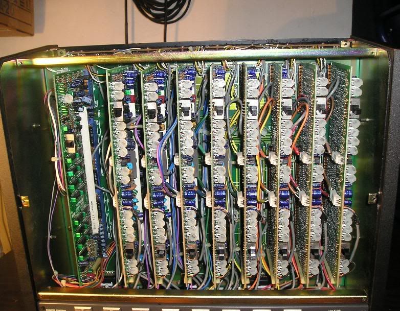
otaripots.jpg


I've been testing out all the channels of my otari 8 track lately. When I was testing each individualy, I noticed some seemes a little stronger than others, so I used the oscillator, and noticed that indeed, some channels were considerably stronger than others, even when all the channels gains were at 12 o'clock.

So immediately thought it may be the pots on each channels card. These are most likely to calibrate many different aspects of the machine, and I was wondering if anyone knew more about this kind of thing. You can't really tell very well by the picture that not all the pots are aligned with each other, and was wondering if that was what was causing this problem.

The pots are the little round white things......
 
Sounds like you need a run-down of the basics of analog tape calibration. So here goes, I'll try to no make you scramble around the hundreds of posts about the topic and confuse yourself :D

I've derived some of this explanation from here: http://www.recordingwebsite.com/articles/tapecal.php , and translated it to Otari-talk.

You need an MRL calibration tape. http://home.flash.net/~mrltapes/pub644.pdf

They may be as expensive as all hell, but believe me, it's a wise investment. Your ONLY true reference for playback levels is achieved with one of these tapes.

It needs to be 1/2", 3 frequency, 15 ips, IEC equalization, the right operating level (+3, +6, or +9, which-ever type of tape you use the most. For example, if you use Quentegy/Ampex 456 the most, get a +6 cal tape to keep it simple. And so on for 499/GP9, get a +9 cal tape. If you switch the type of tape you use later, you do NOT need a matching cal tape, you just need to compensate up or down by the dB difference on the meters.) I bought calalog # 341-644-512-109. It's 1/2" 3-frequency 15ips 72s per tone, IEC equalization, and +6 dB (because I use 456 tape the most.)

(One last note about your calibration tape --- NEVER record over ANY part of it for ANY reason. It's precious shit. :-) Also, it comes in the package tails-out. So to play it back, load it on the right hub, put the take-up reel on the left hub, and thread it. Rewind to the beginning, and go from there. Always fast-forward it all the way when you are finished using it, and keep it STORED tails-out. In fact, you should always store tape tails-out to prevent print-through.)

Clean the heads, and all parts of the tape path, de-mag it, (not-so-common-sense. Just do it before you load you cal-tape, to prevent damaging it.)

STEP 1 of calibration: SET THE REPRO LEVELS: Play back the 1kHz tone on your calibration tape, monitoring all tracks from the repro head. Make sure all SRL (standard-reference-level) buttons are depressed. This bypasses the line-in level knobs. Now take your tweaker, or whatever clever device you have to calibrate your pots, and find the row of pots called REPRO LEVEL. Adjust each pot until all meters read 0dB (GIVEN, of course, that your cal-tape level is equal to the level of the type of tape you wish to use.)

STEP 2 : SET THE REPRO HIGH-EQ LEVELS: Make sure there are no dogs for a 500 foot radius. Play back the 10kHz tone on the cal-tape, monitoring all tracks from the repro-head. Tweak the pots labeled REPRO HI-EQ or something like that, until each of them reads 0dB on the meters.

STEP 3 : SET THE REPRO LOW-EQ LEVELS: I've had trouble with this step on this machine. Refer to the manual. I've tried to adjust it, but nothing happens. My feeling is that the pots labeled REPRO LO EQ adjust the High EQ for the low tape-speed, although I'm not sure. IDEALLY, you'd play back the 100hZ tone, and adjust the Low-EQ curve til it says zero. FYI.

STEP 4 : REPEAT STEPS 1, 2, and 3 ON THE SEL-REPRO HEAD. Monitor from the Sel-Repro (or Sync) head, and repeat those same steps, while of course, tweaking the SEL-REPRO levels appropriately.

STEP 5 : ADJUST THE RECORD BIAS : OK, here's the tricky part. To adjust the bias correctly, find out from the manufacturer what the bias is for your tape. http://www.quantegy.com/Audiorecordersetup.asp is the list for Quantegy/Ampex. This "magic number" is 2.0 for 456, and 3.0 for 499/GP9. FFWD and Put away your calibration tape (TAILS OUT!!!), and load up a reel of regular tape. Let the dog out, and set the Oscillator knob on the left side of the controls to 10kHz. rec-ready all tracks, hit rec-play, and monitor from the repro head. For each track, you need to first turn the bias screw counter-clockwise. As you watch the meter, you will see the needle rise up and then begin to fall back. Let it fall back to the left side of the meter, until it stops moving. Then turn it clockwise until it peaks and begins to go back to the left. Back it up just a hair until it is at the peak point. The point at which it peaks is irrelevant, but will signify the point at which you should begin counting the overbias (or, "magic number"). This means that if your overbias is 2db, then turn the screw clockwise until it has gone down 2db past the peak point. Repeat this for each remaining tracks, while recording the 10K tone.

STEP 6 : ADJUST THE RECORD-LEVEL. Set the oscillator to 1K. Record the 1K tone on all tracks, and adjust the record-level pots, until the meters read 0dB.

STEP 7 : ADJUST THE INPUT-LEVEL. Keep the oscillator at 1K. Monitor ALL INPUT, and adjust the input-level until all meters read 0.

STEP 8 : ADJUST THE RECORD-HIGH FREQUENCY LEVEL. Set the oscillator to 10K, and record it on all tracks, monitoring from the repro head. Adjust the record-High Frequency levels until all read 0dB.

STEP 9 : HAVE A BEER


Good luck!

-callie-
 
That is a very simplified version of that procedure.

This is what the manual says:
Clean and demagnetize the heads and tape guiding components before performing the test and alignment procedure.
The levels indicated in this section are at a 1 KHz frequency at the reference recording level of 250 nWb/m.

Never run the test tapes on speeds other that normal play run (never use the rewind or fast forward mode).
This is further explained below.

During the alignment procedure, the rewind and fast forward modes should not be used.
After alignment, wind the tape completely on the takeup reel, interchange reels, thread the tape, and place the equipment in the play mode to wind the tape back on its original reel.
After extensive use, high frequency tones may drop as much as 2 dB.
In addition, flutter indication may rise even though actual flutter remains unchanged.
Flutter increase is caused by demagnetization of recorded signal from repeated plays, tape deformation due to tape tension, changes in temperature and humidity, and increased dropout resulting from tape wear.

Test Conditions.
The test conditions specified in the following steps are to be met prior to performing the tests.
After these test conditions are met, continue with the following procedures for checking overall signal-to-noise, overall distortion, crosstalk, erasure, tape speed and flutter.

1. Clean and demagnetize the heads.

2. Use high quality low-noise tape such as Ampex 456.

3. Turn the power on and allow unit to warm up for 20 minutes.

4. Be sure the head cover is installed for all tests.


THERE'S ABOUT 6 PAGES MORE BEFORE YOU EVEN GET TO THE FREQUENCY RESPONSE - YOU NEED TO GET THE MANUAL, I AIN'T TYPIN' THIS WHOLE THANG.

skipping to the frequency response ELECTRONIC ALIGNMENT section:

Since the reproducer equalizer circuit has high frequency independent controls for both 15 ips and 7.5 ips, an adjustment is made at first for 15 ips.
Table 7-3 shows the time constant and fluxivity at each equalizer.

1. Connect the ac voltmeter to the LINE OUTPUT connector

2. Thread the test tape through the equipment.

for 15 ips:
3. Reproduce a 500 Hz signal on test tape.
At this time the value on the ac voltmeter is decided as standard.

4. Reproduce the frequncy response test signal (from 31.5 to 20 KHz) and note the reading on the ac voltmeter.

5. Adjust the VR 102 adjustment controls with a frequency of 10 KHz for a 0 dB reading on the ac voltmeter.
The reading should be 31.5 Hz to 20 KHz at +2dB.

SLR (repro Level) Adjustment:
1. Connect the ac voltmeter to the Line output connector.

2. Thread the 15 ips test tape through the equipment.

3. Reproduce the reference recorded flux on the test tape and adjust the VR 105 adjustment controls for a +4 dBm reading on the ac voltmeter.
(Line Level switch is in the HIGH position)

SEL/REP Level Adjustment:
1.Set each monitor switch to the SEL/REP position.

2. Reproduce the reference recorded flux and adjust the VR 101 adjustment for a +4 dBm reading on the ac voltmeter.

Record Head Azimuth Adjustment:
The head azimuth may be adjusted at a low tape speed for critical head alignment and at 10 dB below the standard recording level.

1. Connect the ac voltmeter to the LINE OUTPUT connector and connect the audio oscillator to the EXT OSC jack.

2. Set the TEST OSC switch to the EXT OSC, the LINE OUTPUT LEVEL switch to the HIGH position, the LINE INPUT LEVEL switch to the Low position, and MONITOR switch to the REPRO position.

3. Thread a blank tape through the equipment.

4. Set the audio oscillator frequency to 1 KHz.

5. Place the equipment in the record/reproduce mode and adjust the INPUT control for -6 dBm on the ac voltmeter.

6. Adjust the record head azimuth screw "A2" for a maximum reading on the ac voltmeter at a frequency of 15 KHz for 7.5 ips record/reproduce mode.

7. If a maximum reading can not be achieved within one full turm of the azimuth screw, or a maximum reading on the ac voltmeter is well below -6 dBm, a full head alignment may be required.
Refer to section 8.

RECORD BIAS Adjustment:
The record bias should be set at 3 dB over bias at 10 KHz for low distortion and high maximum output level.
The overall frequency may be adjusted with the RECORD EQ, the RECORD BIAS, and LOW F. COMP. adjustment controls for flat frequency response curve.

1. Set the tape speed to 15 ips, and set the MONITOR switch to the REPRO position.

2. Record and reproduce the 10 KHz signal of the TEST OSC and adjust the LINE INPUT control for a =4 dBm reading on the ac voltmeter.

3. Adjust the RECORD BIAS adjustment controls (VR 205) for a peak indication on the ac voltmeter and then turn the RECORD BIAS adjustment controls clockwise until a decreased level of 3 dB is obtained.
The standard biasing point of the MX5050 MKIII - 8 is at 3.0 dB overbias at 10 KHz for 15 ips.

Do you want me to continue with the OVERALL FREQUENCY RESPONSE adjustment section? AND THERE'S A VU METER ADJUSTMENT SECTION.
 
Hello!

I really hate to differ or take issue with such a well delineated analog calibration website,... but I've seen that page before, and I take issue with some specific things about "levels".

In brief,...

Quantegy 456 is a "+6" tape, sure, but that's it's MOL, (Maximum Operating Level), the maximum point of saturation, above which distortion will occur. Therefore, the site recommending adjusting your tape drive to "0VU=+6db/185 (370nW/m^2)",... I believe is wrong. Instead, you'd want to set your "0VU" point at "+3db/185 (250nW/m^2)", so that you have a +3db above 0VU "headroom" on the meters, before you hit the hard-clip limit (MOL) of +6db/185.

Likewise, for Quantegy 499, a "+9" tape, (MOL), you'd want to set your "0VU" point at "+6db/185, (370nW/m^2)", to leave the same +3db above 0VU "headroom" on the meters, before hitting the MOL of +9db/185.

That you set a recorders "0VU" point at the tape's MOL is a common misconception that I've seen perpetuated on the web, over & over,... & it's just flat out wrong. I've seen it cause users problems too, based on the occasional "help me!" post on boards like this.

Hence, recorders like the Tascam 38, 388 and most Fostexes specify "0VU=250nW/m^2", while specifying "Ampex 456" tape.

I hope that info is clear & makes sense. If not, then please let me know.

Thanx & have a nice day!

PS: The quip out of the Otari manual, posted by our friend, above, is correct,... to set the 0VU operating level to "250nW/m^2" for use with 456. That's a common setting for decks of the era.
 
Last edited:
Well well well...........Nice to see a direct statement from the manual. I may rethink/redo MY otari calibration if it doesn't sound right once I set everything up and use it....
 
REEL BUZZER, I have a question...

The manual states hooking up an AC voltmeter to the tape-outs for the calibration.

I have a multi-meter which will read volts, but it doesn't read volts in terms of dBm, or dB. (At least.......I don't THINK it does.) Can a multimeter be used for that part of the calibration? Or is there another piece of test gear I have to invest in to get the job done properly?

Also, does this mean I have to get a $210 multi-frequency MRL tape?

(I think y'all have finally slapped me in the face pretty good, and gotten rid of my anal-retentive calibration mentality. I now understand that narrow track-width format machines need to be toned down for the best performance. Dunno why I couldn't get that trhough my head before.)
 
Muckelroy said:
I have a multi-meter which will read volts, but it doesn't read volts in terms of dBm, or dB. (At least.......I don't THINK it does.) Can a multimeter be used for that part of the calibration? Or is there another piece of test gear I have to invest in to get the job done properly?

You say your meter reads VU's.
Maybe someone here knows a convertion chart. I don't.
But I think that -6 dBm is = to -10 VU.
If you can, use an Ac Voltmeter Hewlett Packard 400E or 400FL or similar.


Also, does this mean I have to get a $210 multi-frequency MRL tape?

You need a test tape to reproduce the 500 Hz/reference recorded flux/and for the frequency response test signal/SRL (repro level) adjustment, etc.

You need a blank tape and an audio oscillator for the record head azimuth, record bias, signal to noise, & overall frequency response adjustments.


A couple of routine maintenance tools to keep next to the machine:

Bandpass filter
Flutter meter
Wave analyzer
Volt-ohm meter
 
Back
Top