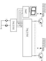
And here is what I ended up doing. This is not a schematic mind you, but an idea. I never drew out the schematic electronically, but sketched it on paper the old fashioned way
")
Essentially, using three TTL chips, I can use an "up" switch and a "down" switch to select 1 pair of speakers out of 16. I don't have 16 pairs of studio monitors, but this design supports up to that many. The 74LS193 is a binary encoded decimal (BCD) counter, that counts up or down based on pulses from the two switches. When you power the circuit on, I have a little capacitor and resistor (not shown) off the 74LS193 that defaults the counter chip to the first pair of speakers/monitors, so if I do nothing, I'd be using my main monitors.
The 7447 chip simply displays on a single digit LED display, the number of the monitors I am utilizing. "0" is default, and it counts to "9", then displays "A", "B", etc to "F".
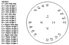
The 74LS154 decodes the BCD output, but instead of displaying it on a LED display, it activates a low (ground) output, of which there are 16, to indicate which number is presented at its inputs. These outputs drive transistors, which drive relays, which have 5V coils and heavy duty 20A 4PST contacts, thus able to switch out the positive and minus leads, for both monitors no problem.
Probably gross overkill, but it was my solution to the multiple pairs of monitors problem. I specifically wanted the "default to this pair" feature, and this circuit made it easy. Also, I had everything including the relays in the junk drawer, so the "cost" was a blank 1U panel to drill and cut, some standoffs for mounting the perfboard that the two switches and the LED display are on, and some black paint to hide all the scratches I made while cutting and drilling the panel. Totally slopppy point to point wiring, but it works fine.