More on the INA217 etc....

  • Thread starter Thread starter OneRoomStudios
  • Start date Start date
This schematic is one I came up with. It was based on the tech data sheet though.
I believe I posted it already. Do a search of my forum name. It should come up. If you have trouble reading it, I could probably send you a digital photo of it.

Bob
 
Thanks Bob, I actually saw that thread before, I just didn't make the connection. I wish I knew how to etch PCB's because direct wiring all this stuff is going to be a pain in my ass. I could go the way you went - I might be able to rip out the guts of an ART MP, but I don't know if the circuit would work for the new design. Any thoughts anyone?


Or anyone want to etch a PCB for me? :D
 
OneRoomStudios said:
Thanks Bob, I actually saw that thread before, I just didn't make the connection. I wish I knew how to etch PCB's because direct wiring all this stuff is going to be a pain in my ass. I could go the way you went - I might be able to rip out the guts of an ART MP, but I don't know if the circuit would work for the new design. Any thoughts anyone?


Or anyone want to etch a PCB for me? :D

Well I've got my first PCB staring at me unetched, but I bought all the supplies, it's pretty cheap and it doesn't sound too hard . . . make circuit diagram with freeware, expose, etch . . . a bit like developing film if you've done that.

Maybe somebody that's done this can chime in?
 
i dont know if this will help, but there are various places on the net.
its been awhile - so just google. that let you download free software
where you draw your circuit out. then you upload your finished circuit,
and they ship you finished raw boards. i dont know how good they are however.
 
mshilarious said:
Maybe somebody that's done this can chime in?
Well, I just do it the cheapest, dirtiest, fastest way. Not the prettiest boards in the world, but perfectly functional.

You need:
1) A plastic or porcelean tray larger than the board to etch it in (throw-away ziplock type food containers work fine)
2) Ferric chloride or other etchant (get at RS or local electronics store - ~$5.00 for 16 oz or so - enough for several boards)
3) Copper clad board (again at RS <$5.00 for sizes up to 6X8" or so)
4) Sharpie extra fine point marker - the one known as "Industrial" works best - more resistant to etchant

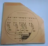
From the schematic, draw out the traces you will need on pencil and paper. Make sure parts sizes match your traces (for this reason it's better to have your components available for sizing - different resistors and especially capacitors can come in random sizes)

Once you have that drawn, then you need to copy it (by hand) with the marker to the copper clad board. Make sure the board is clean and has no oil residuals on it - I wash it in soap and water pror to marking, and try not to let my hand or fingers touch it.

Pour etchant into the tray, and immerse the board face up in it. You just need enough to cover the surface. You can heat the solution with a hair dryer to get faster action. Here in Arizona I just do it outside in the summer - 110F seems to be a good temperature. :) Rock the tray slowly back and forth to agitate it.

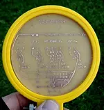
When all the copper's gone (it will etch faster on the edge, slower to center), remove the board and wash in water. You can remove the residual marker with steel wool or similar.

Next drill the mounting holes with a small drill (#60 or thereabouts I think - they only have to be big enough for the leads to go through)

The board is done. Dispose of the etchant according to your local regulations - the copper chloride now in the etchant is toxic to fish and other environmental flora and fauna - don't flush it down the toilet. I keep mine in a plastic jug that I haven't figured out what to do with yet. :)

Attached are before and after pics of a board.
 

Attachments

  • micboardbefore.webp
    micboardbefore.webp
    32 KB · Views: 199
  • micboardafter.webp
    micboardafter.webp
    46.1 KB · Views: 209
Oh yeah I thought I recognized that circuit. Any luck improving the diaphragm on that mic?
 
Here's another question, if pin 5 goes to ground, where does pin six go?
 
OneRoomStudios said:
Here's another question, if pin 5 goes to ground, where does pin six go?
I don't understand. If we're still talkng about the 1NA217, pin 6 is the output. It goes to the next stage of your signal chain, which you could consider as going through a load to ground.
Just cut out the circled crap and ground pin 5.

mshilarious said:
Oh yeah I thought I recognized that circuit. Any luck improving the diaphragm on that mic?

Actually, I got a nice stretched diaphragm. The problem is that the sensor phototransistors are way too noisy, so I'm trying to work it out using photodiodes, but due to recent adverse events in my life I haven't been able to spend time on it. Maybe soon.
 

Attachments

  • 1na217servodelete.webp
    1na217servodelete.webp
    9.4 KB · Views: 315
Thanks for the help Doc - I was thinking too much and got myself confused.

So as far as I understand now, the pin layout is this:

1 - ?
2 - goes to R6
3 - goes to R7
4 - goes to C2/-15v
5 - goes to ground
6 - goes to 0v
7 - goes to C1/+15v
8 - ?

Is this right? What are pins 1 and 8? Sorry for all the questions, I'm still trying to work this out. Thanks again for all the help.

-Peter


PS - Sorry to hear about the adverse events, you seem like a good guy, it's too bad the shit happens to the good people.
 
Pin 2 is the inverting input - it comes from pin3 of the XLR through C1, and has two 1N4148 diodes connected to it. Pin 3 of the 217 is the noninverting input and gets the other half of the balanced signal from pin2 of the XLR. The circuits connected to the 217's inputs - pins 2 and 3 - are identical.

Pins 4 and 7 are the power supply pins - +/-4.5 to +/- 18V - the negative voltage to pin 4 shold be the same as the positive voltage to pin 7.

Pin 5 is the offset voltage trim for the output, which is pin 6. This is used if you want to add some DC voltage to the output signal - in this case, you want none, so pin 5 can be grounded (at 0 volts.)

Pins 1 and 8 adjust the gain by a resistance between them. You can see from the attached schematic from the spec sheet that no connection between them (infinite resistance) gives a gain of one, or unity gain. Lowering the resistance increases the gain to a maximum of 66dB at 5 ohms.

The preamp in the spec sheet varies this resistance from 8 to 1608 ohms, for a range of about 15 to 60 dB by turning the potentiometer R7 (wired as a variable resistance).
Note that R6 and R7 are not connected to pins 2 and 3 but rather between pins 1 and 8. The schematic is not very well drawn in this area.

Hope this helps.
 

Attachments

  • 1na217_gain.webp
    1na217_gain.webp
    26.5 KB · Views: 255
Last edited:
Thanks a ton for explaining this to me, I know it's probably obvious and annoying to go over, but I just wasn't getting it. In fact, I'm still slightly confused. You said, "R6 and R7 are not connected to pins 2 and 3 but rather between pins 1 and 8." But on the schematic, R6 is labeled (2) and R7 is labled (3). Are those numbers refering to something else besides pins? If so then what?
 
I believe I've made a few updates to that drawing since that posting.
You'll also need a wall wart to make it work. I got mine from Parts Express. Their p/n 120-1150.
This is an advanced project for a novice if you are trying to do your own layout and put it together from scratch. If it was prepared as a kit, then it would be easy to put together. I used the MP105 because the stripped out board and housing made it go alot easier than having to breadboard or make your own artwork and housing. You really need a complete metal enclosure rather than a plastic box.
Maybe I should turn it into a kit. I'm happy with the result, no capacitive distortion, low noise, high quality components. It's not the ulitimate in high end but it sure beats any of the lower end preamps. Why would a home recordest who does this as a hobby need to spend more? I'm simply stunned at the parts used in gear, even expensive gear too. A design does not have to be fancy, just use high quality parts and a smart layout and you've got a decent product.
But it is a fact too. Alot of guys are messing with mics and preamps (myself included) but if your convertors are low end, you really won't hear the detail your DIY mics and preamps are capable of. Good convertors are expensive and low end ones do not lend themselves to DIY activity to improve them. I've found it to be a catch-22.

Bob
 
Hey Bob, how well do you think an ART tube MP would work as a box and board? How dificult is it to re-route (or re-plan) the cicuits on an old board? Any info on that would be awesome since I'm not too keen on making my own PSU or box.
 
OneRoom, I believe that box is plastic which helps contribute to its noisyness problem. I used some of the existing artwork (traces) to make my pre. I was able to do that because I reversed engineered it. That means I traced the circuit out and drew the schematic by following the artwork and reading parts values and names. If you don't have any experience at doing this kind of thing from scratch then I wouldn't recommend building it. You could well end up with problems you won't understand.
I have been considering this as a kit at some future date and maybe that could happen. I really like doing this stuff and it would be a natural for me. I believe many people in your situation want quality DIY stuff without breaking the bank. TubePres, BlueTubes, Art Tube MP, MP105, etc, etc, just do not cut it. They lack dynamics, may be noisey and are subject to smearing and phase distortions that make creating a mix with them very tough. The Mackie VLZ is a classic example. It LOOKS really solid, and it is, BUT they use tons of shit capacitors and the worst op amps in the world, New Japan Radio stuff. They are a-holes in my opinion. Thats why it doesn't track well and people don't have a good opinion of it as a recording desk.

My two pennies,
Bob
 
Yeah a kit would be awesome. The MP box is metal, but I definitely would have a hard time trying to re-map the circuit on to exsisting traces. Maybe I can get a PCB that will fit in the MP box. My only concerns would be the power supply, the phase switch (which I would like to have but don't understand how to build just yet) and the pad - same deal as the phase. I really wish there was a good electronics class I could take for cheap. Unfortunately I don't have time for another class right now anyways. Thanks again for the help.
 
just as aside. when using capacitors. try and use low tcr types.
also ive found differences using ultra low noise metal film resistors.
also in that circuit if it uses bypass caps on the INA power pins. try and mount close to the power pins if you can. keep leads short.
if using electrolytics. ensure you use low leakage types.
for example if you use the 47 mf electrolytic types.
also when using capacitors watch that the voltage is above the power voltage by a significant margin. double i seem to remember.
but bob correct me if i'm wrong.
ive forgotten the exact calculation.
there is a type of low noise resistor that looks like a small black planar cell
with two leads coming out the end. ive forgotten the brand. used in
critical circuits. they are quite nice.
bob. how do you do the bipolar supplies. ??
this is the part i find a pain. do you buy a wall wart already bipolar so you dont have to make one ? if you do - please tell me who makes these.
i'm getting tired of bipolar supplies.
 
Back
Top