So, the twists and turns this story has taken, it's almost like a Cory story.
The other 238 turned up today. I had to take some pics of it.
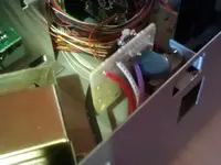
Somehow.......I don't know how, the unit underneath all of this shredded up cardboard, was intact and looked undamaged. I plugged it in expecting it not to work, and it came to life. I put a cassette in that had some 8-track stuff on it from the 688 and amazingly it all seemed to work.
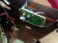
I then decided to take the hood off it to compare the transformer with the European model I had bought. It was then I noticed the '220V' tag on the rear of this unit. So THIS ONE was a European model also and I'd just happily plugged it into the 240V UK. Once the cover was removed, it was confirmed this was a European model with the violet wire from the transformer in the +ve position. I resoldered the red wire to the +ve as per the UK specs and tried the unit. Everything was fine, I hadn't blown the unit so I set about putting the unit in the rack and trying it with the Soundcraft Spirit desk. After making a new recording, I took the tape out and tried it in the unit I'd bought from The Netherlands. Strange....the unit is playing back at half speed. I then checked the manual to make sure there wasn't a setting that I'd forgot about. This unit has had the capston servo board replaced. I remeber reading that this board also served the 122 machine (which I think is a normal speed cassette machine) and there is a mark on the board to select 4.8cm/s or 9.6cm/s. You choose one of the settings by soldering between two semi-circle jumper positions (something I've never seen elsewhere). I took the unit out of the rack, but not before making a spoken recording to see if all other things being equal, the unit was performing as it should now I'd finally got it powered on. It was funny seeing the tape turn so slowly, but it did make a fine recording on all 8 tracks. I was half tempted to leave it as was, but then curiosity got the better of me, so I removed both units from the rack so I could compare boards.
I then used Cory's excellent instructions to get the board free from the Dutch machine and as I suspected, the solder was covering the wrong selector position. A quick desolder and careful resolder of the right position and the deed was done. I put the machine back together and found comparing it to the other machine, that the Dutch machine was running slightly quicker than the Glasgow machine. As neither machine has been set up correctly I may have to come up with a way of bringing them within spec of the 688 as well....as it is, the varispeed on the machines will enable me to do stuff. The manual mentions a TEST TAPE and a 3000Hz tone and a counter of kinds.
Any ideas how I might be able to calibrate between machines using a multimeter (a very good Bryson one) and a scope?
So, to recap, so much for me not wanting to open up the 'like new' machine. I end up doing a 'repair' on a new board because it had been setup incorrectly. I was thinking of reaching out to the Ebayer concerned, but it isn't like the unit was faulty or not as described. The hassle sending it all the way back to Europe when I knew what the problem was, just wasn't worth it.