INA217 and input transformer

  • Thread starter Thread starter Ettos
  • Start date Start date
E

Ettos

New member
Hi all,
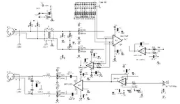
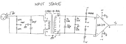
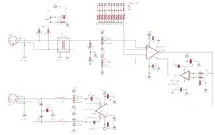
I've built a microphone preamp around the INA217 chip. Now I'm concentrated on the input stage to replace the old DC blocking caps with an input transformer. I like very much the Cinemags' sound (audio clips here for comparison).
I'm asking you if the circuit you see on the schematic I attached could work or not (with a CMMI-8PCA Cinemag input transformer).

Thank you so much for your help!
M.
 

Attachments

  • in_stage.webp
    in_stage.webp
    27.7 KB · Views: 428
R2 & R3 are way too small. The impedance seen by the mic will be those resistors divided by the square of the turns ratio, in parallel with the phantom resistors (which as drawn in this case hardly matter).

I'll let you solve for that and adjust accordingly :)

You are also committing to +18dB minimum gain, possibly plus some additional minimum gain at INA217 (you didn't show its gain resistor solution). So you might want to incorporate a pad.

Anyway, INA217 is quiet enough that you will probably be hitting a current or thermal noise limit. I would look at a lower ratio transformer.

Your un-numbered input RF filter caps; you need to be a bit careful there. You probably don't want to match caps, but if you don't with that scheme you could potentially degrade RF rejection. You probably don't even need those given the transformer, but if you want them I would use the scheme shown in the INA217 datasheet.
 
R2 & R3 are way too small. The impedance seen by the mic will be those resistors divided by the square of the turns ratio, in parallel with the phantom resistors (which as drawn in this case hardly matter).

I'll let you solve for that and adjust accordingly :)

[cut]

Thank you for the hints.
So, I can replace R1 and R2 with 10K resistors and obtain an input impedance of 2.3K. This should be better I suppose. I don't exactly know the typical range for this impedance but I read it should be around ten times the mic impedance (i.e. AKG414 is 200 Ohm)...
Anyway, do you think is it better to choose a transformer like this one (1:1 ratio) ?
Is there a way to choose a proper ratio transformer? Jensen recommend to select the optimum secondary impedance by dividing the amplifier voltage noise by the current noise. For INA217 it gives me 1.6K, so I would choose for example a CMMI-3.5C with 1:3.5 ratio (9.7dB step up), or Jensen JT-11K8-APC.
Thank you again.
M.
 
Last edited:
(10000 + 10000) / (8^2) = 313 ohm.

With a 1:3.5 transformer, that would be a more reasonable 1.6K.
 
Schematic

I made a first attempt drawing the complete preamp schematic. It is almost based on the one provided by Seventh Circle (T15 model), plus I added the input transformer (Cinemag CMMI-3.5C) and removed the RC filter caps on the input. In the schematic there are two servos: input and output. The input servo is made to reduce DC transient when switching gain.
For R5 and R6 I used two 15K resistors, obtainig (if I did the correct calculation this time) around 2K differential input impedance (with phantom ON).
I would really appreciate your comments and corrections!
 

Attachments

  • preamp_1.webp
    preamp_1.webp
    60.5 KB · Views: 383
Hmmm. The input servo is an awful lot of trouble where a 100K resistor would probably work about as well. You can't record through a gain change anyway.

The output trim control has a really limited range. Its buffer has a DC offset trim and no gain, which makes me wonder why bother with the preceding servo.

Basically, you have dedicated a lot of parts to correcting things that might never really be a problem, especially if this box is going to live in a studio rather than a more adverse environment (bad EMI, long cable runs, etc). I think I would measure DC offset at INA217 before I committed to the more complicated scheme. We are probably talking about a difference in headroom of at most 1dB (probably less), and if this amp already has more headroom than your converter (it probably does), it's not going to help.

I would stick the clamping diodes and a 47 ohm resistor on the output, then do an impedance balanced output with another 47 ohm resistor. That's gonna be plenty of CMRR for a line-level output in a studio; if you get induced noise on that it's probably impossible to play an electric guitar in that room. I would direct couple that to the converter . . . which probably has an input capacitor anyway (converters are almost always single-ended devices, which means they need to couple their half-rail bias to the incoming audio signal).
 
Hmmm. The input servo is an awful lot of trouble where a 100K resistor would probably work about as well. You can't record through a gain change anyway.
Ok, you convinced me to remove that input servo. Using the preamp in studio, I don't need to change the gain "live". I will use a make-before-break switch to reduce clicks...


The output trim control has a really limited range. Its buffer has a DC offset trim and no gain, which makes me wonder why bother with the preceding servo.
Basically, you have dedicated a lot of parts to correcting things that might never really be a problem, especially if this box is going to live in a studio rather than a more adverse environment (bad EMI, long cable runs, etc). I think I would measure DC offset at INA217 before I committed to the more complicated scheme. We are probably talking about a difference in headroom of at most 1dB (probably less), and if this amp already has more headroom than your converter (it probably does), it's not going to help.
This is another good point. Actually, I don't even need a "fine tuning" gain so I can remove this block as well. Anyway I'm going to keep the output servo, as the INA has some important DC offset, I measured that on an old circuit that I made, based on the INA datasheet schematics.


I would stick the clamping diodes and a 47 ohm resistor on the output, then do an impedance balanced output with another 47 ohm resistor. That's gonna be plenty of CMRR for a line-level output in a studio; if you get induced noise on that it's probably impossible to play an electric guitar in that room. I would direct couple that to the converter . . . which probably has an input capacitor anyway (converters are almost always single-ended devices, which means they need to couple their half-rail bias to the incoming audio signal).
Sorry, I can't understand this part. On which output would you insert clamping diodes and how? And the 47R resistors?
How to do to direct couple?
You really must have got a huge dose of patience to keep answering my questions! :D
 

Attachments

  • preamp_b.webp
    preamp_b.webp
    47.9 KB · Views: 359
Back
Top