In-Line Recording Console - Flow Chart for Signal-Flow

Hello. I'm learning about recording consoles, specifically a classic in-line recording console at the moment. Is anyone familiar with the flow charts used to track the signal-flow for these analog recording consoles? I have to create a flow chart for one with these I/O controls and specifications:

  • mic preamp/trim
  • small fader
  • large fader
  • large channel input trim
  • small channel stereo pan pot
  • large channel stereo pan pot
  • VU meter
  • large channel aux send pot
  • small channel aux send pot

  • tape switch
  • mic switch
  • small channel mute
  • large channel mute
  • -6 dB pad
  • EQ switch
  • direct "DIR" switch
  • "24" switch
  • pre/post aux send switches

Keeping in mind that:

1. Under normal conditions, the mic preamp feeds the small fader path, which can be assigned to the stereo bus; the multitrack feeds the large fader path, which can be assigned to both the multitrack busses and the stereo bus. The large fader path feeds the direct out, post fader.

2. The "24" switch gives the small fader path access to the multitrack busses, instead of the large fader path. Both paths can still be assigned to the stereo bus.

3. The tape switch feeds the multi-track signal to the small fader path (in addition to the large fader path).

4. The mic switch feeds the mic preamp output to the large fader path (in addition to the small fader path).

5. The EQ switch puts the EQ into the small fader path, instead of the large fader path.

6. The -6 dB pad affects the return from multitrack only, but will affect both the small and large fader paths when the tape switch is engaged.

7. The VU meter can be switched to indicate any one of the following: small channel input level, large channel input level, or direct output level. This last selection reflects any changes made through the large channel fader.

8. The mute switches cut the post-fader aux sends, but not the pre-fader aux sends.

9. The mute switch in each path will cut the direct out and/or multitrack bus signal when either of these are being sourced from that path.

10. The "DIR" switch gives the small fader path access to the direct output post-fader, instead of the large fader path.


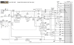
The attached image is an example I am supposed to create my flow chart similar to, of course, mine can be a little less detailed.

This is all very new to me, so I'm basically just asking for some help as to where certain things should go and meet with other things (in terms of the symbols and stuff). If anyone understands this sort of thing quite well and could help me make sense of it, I also have Discord and I could communicate there easier and give more examples of what I'm going for.

Thank you!
 

Attachments

  • Screen Shot 2022-10-23 at 11.18.11 PM.png
    Screen Shot 2022-10-23 at 11.18.11 PM.png
    408.6 KB · Views: 11
I assume you are on some kind of audio course? Flow charts have been, for me, only useful when you get stuck, sitting in front of the desk - because if you can see the metering on the multitrack and have a couple of mics attached to adjacent channels, pressing buttons and turning knobs ALWAYS make more sense than routing issues.

I don't quite understand what you are asking? You have the flow chart, so why are you creating another? When we moved from in-line consoles, it made a great relief -especially students who would need to learn two different ways of working. I preferred the version where we had inputs and then send/returns, but having both paths on one bigger strip was the favourite of others.

Tell us what you need, because you seem to have answered the usual question yourself. Tell us which thing you think you may have misuderstood. If this is a college set question, then maybe you are supposed to sneak into the studio and test your conclusions and fix things you may have misunderstood. After all, one of us has the 3000 to prod, and that isn't me (thankfully)

I wasnt aware the history of consoles was being studied any longer, but I suppose if you still have a working one, history is good for background.

Just ask your questions. You said " I'm basically just asking for some help as to where certain things should go and meet with other things (in terms of the symbols and stuff" but the flow diagams show that, don't they? That's kind of their purpose. I assume you understand the basic principle of how these desks were used? In essence, the most sophisticated channel strip controls used for the vital stuff - so your mics coming down through the primary route, and any off tape monitoring, during track laying coming back on the minimalised strip controls - then when tracking is complete and you start to mix, the sophisicated and easier to access controls are for replay from tape, and any live mics being used are relagated to the 2nd set? With these two differences in mind, the flow diagram shows you how they migrate through the mixer. You get this bit, right? It leave me still confused where you need help?
@rob aylestone Hello there. Sorry for the confusion, but what I'm having trouble with is creating the rest of the flow after the mic input leads to the mic preamp/trim. Yes, I have a flow chart example (the one I attached), but the reason I have to draw my own flow chart is because mine will be similar to that one, but slightly different, according to the bulleted list of specs my console flow chart must have. I'm just having a hard time understanding what all I will have in the channel path and the monitor path. I could use some guidance as to how to draw it because I've never really drawn a flow chart like this so I've been very stuck.
 
But the flow chart is already done? You've uploaded it and I saw it. Your list seems to match the flowchart in terms of what each section/control does. It clearly shows the route from the mic input, through the preamp, filters. polarity swap, EQ and the two possible paths - one through the rotary pot and the linear fader through to the left/right or sends depending on the way you set it. some things appear to be missing - the 6dB pad for instance. No idea where in the flow that goes. The direct out comes from either the bus or the output of the routing section.

I think you need to explain what your stumbling block is. How have you drawn your version of how the signals flow. Maybe if we see how you are thinking we can put right any errors? Why do you need to do this? Are you learning to operate vintage kit as a history element in a course? I'm not sure the effort in learning obsolete systems is mainstream enough to teach. It's important for those of use who love old gear, but most younger people cannot even remember when DAWs didn't do audio?
 
It appears that he posted the flow chart for a Sony MPX 3000 mixing console. The OP needs to lay out his own design, but is stuck on how to approach the problem.

My suggestion would be to first take the "small knob" side and follow all the routings you need for that side of the strip. Print out your list and highlight each "small fader" instance, and complete that part. Then do the same for the "large fader" portion. At some point they intermingle, but you just add those tie-ins as you go.

Flow charting isn't a single step process. You'll probably do at least 3 or 4 iterations. We used to do it on a white board (flow charting chemical processes and procedures for ISO9000 was a fun time... NOT), and you always have multiple edits. In any case, you need to just follow the steps you've been given. Eventually, you'll have all the steps covered.
 
Aah, I see. That’s a bit of a chore. I wonder what the desk is? I messed the whole point it was an example. I suppose you’d have to make sure at least one of every type of output was monitored in some way, so you could see when the feed to the control room output changed, or the solo bus, or headphones, let alone all the directs, groups, tape outputs etc, the. You’d have to do the same for inputs then. Wow!

I think I’d cheat. Find the manual, then redraw the diagram so it looks different, leaving out a few you had not thought of. That’s cheating, but the entire exercise is making you think, so still valid.
 
The student will never become a clever dick unless he does his own coursework.
If you want to know your way around an analogue console, go to the major manufacturer's websites, and download their
manuals. They often describe the signal flow.
As you already have a flow diagram, start with that, and consider each of the 10 requirement points in turn,
and see how you might modify the diagram to fit the requirements.
 
The OP might also avail himself of a copy of Duggy Self's Small Signal Audio Circuits. That has a lot of information and diagrams of console signal flow systems and a good explanation of how different ways of 'grouping' sources can improve the overall noise performance.

Dave.
 
There is of course the purpose of the person who set the question. Work out what exactly did they have in mind, and why? There is no need whatsoever for people to learn this if they will never use it in work, when that happens. As in teaching people Morse Code - it's not used any more for communications so teaching it is often a preference of a teacher. As in it's knowledge building and a test of resourcefulness. Downloading the manual always gives flow diagrams, so maybe it's a test of research ability, and not a test of understanding elderly out no longer used pathways within mixers? We no longer teach Ohms Law or resonance forumiii to people who want to mix sound. The link between filter design and Q having been lost, bar the use of 'Q' in many plug-ins. So get in the teacher/lecturers mind and work out what the real point was - and work to that. A re-drawn flow diagram could keep them very happy. Unless you are getting graded on using an elderly console practically, is it worth learning something that for most people is totally pointless.
 
The student will never become a clever dick unless he does his own coursework.
If you want to know your way around an analogue console, go to the major manufacturer's websites, and download their
manuals. They often describe the signal flow.
As you already have a flow diagram, start with that, and consider each of the 10 requirement points in turn,
and see how you might modify the diagram to fit the requirements.
I no way did I ask for someone to do the coursework. I’m just looking for a bit more guidance than I feel I’ve gotten in the console area. I’ve been researching a lot fyi. Thank you still though.
 
No Rob! We MUST continue to teach Morse code because we never know when we might be invaded by aliens from outer space!

Dave.
 
One thing that might help is looking at how signal flows through a split console first. This is far easier to visualise because the signal effectively flows in a U shape in a split console - coming in and down the channel strip on the left, going across the bottom and then up out through the groups on the right of the console. It then comes back in from the tape machine on the right, flows in another U down the monitor strip and then back to the middle where it flows up and out of the control room/main outs. Some consoles have the master section on the right so the signal path is effectively a W.

Inline consoles mix all this up together and allow you to share parts of the circuit between two different signal paths which makes things very confusing if you aren't clear about what is going on in the first place. Split consoles are far easier to understand.
 
Back
Top