Help - My AT2035 - Life Alert - Wiring

Teapole

New member
So I was having grounding issues with my AT2035 condenser and I decided to pop it open and look at it. Turns out there was a loose wire connection. While I was fiddling with it the other wires popped off as well. Now I'm not sure what goes where and how to get it working - at all - again.

Oh boy.

What I've tried so far is this. Assume left = 1 Assume top = 2 Assume right = 3 and Red - White - Black are R - W - B respectively.

1R 2B 3W - 1W 2B 3R

I couldn't find much on the internet regarding someone taking the microphone apart or wiring diagrams. So now I'm here. Appreciate any help I can get! Here are some pics!
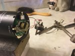
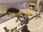
IMG_0118.JPGIMG_0117.JPGIMG_0116.JPG

thanks,

Teapole
 
Last edited:
Update

So I was having grounding issues with my AT2035 condenser and I decided to pop it open and look at it. Turns out there was a loose wire connection. While I was fiddling with it the other wires popped off as well. Now I'm not sure what goes where and how to get it working - at all - again.

Oh boy.

What I've tried so far is this. Assume left = 1 Assume top = 2 Assume right = 3 and Red - White - Black are R - W - B respectively.

1R 2B 3W - 1W 2B 3R

I couldn't find much on the internet regarding someone taking the microphone apart or wiring diagrams. So now I'm here. Appreciate any help I can get! Here are some pics!
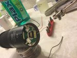
View attachment 96794View attachment 96793View attachment 96792

thanks,

Teapole
I feel like I've tried every combination of the three wires. One time I was getting a buzz, but no voice registering from mic. Really stumped here, and frustrated. At one point the red wire came out from the board end, it seemed like I got a good resolder on it.
 
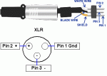
Pin 1 should be ground and would likely be the black wire (ignore the black wire in the diagram below, it's a cable color and the shield is ground). You would need an ohmmeter to verify this between the black wire and the mic's metal body. Pin 2(+) and 3(-) are signal wires (think those are the white and red) and if wired backwards will reverse the phase of the output. If you've tried different combinations with 48v phantom power applied it's difficult to know if applying phantom power to the wrong connections may have damaged something.

XLR-connector-wiring-diagram.gif
 
Last edited:
Pin 1 should be ground and would likely be the black wire (ignore the black wire in the diagram below, it's a cable color and the shield is ground). You would need an ohmmeter to verify this between the black wire and the mic's metal body. Pin 2(+) and 3(-) are signal wires (think those are the white and red) and if wired backwards will reverse the phase of the output. If you've tried different combinations with 48v phantom power applied it's difficult to know if applying phantom power to the wrong connections may have damaged something.

View attachment 96795

Thanks,

I think I'm just out of a mic now, really stupid. The design is very, very cheap and hard to work with. This mic has done really well for me in the past, so it's disappointing.
 
Back
Top