I have slowly, over time, built my system to be a balanced system. Make most of the cables myself, some installed in bedroom walls.
It's all a personal choice, but I really get irritated, when people state things as if they were electrical theory facts, when they are not.
Balanced systems are not designed to add quality, only reduce any noise & interference.
Balanced is defined in terms of the impedance of the two signal conductors with respect to a reference, which is usually ground. If these impedances are equal and non-zero, the system is balanced. If the impedances are unequal the system is unbalanced. A signal conductor with a grounded return conductor is, therefore, an unbalanced (sometimes referred to as single ended) system. Now, A small, common-mode, 60 Hz noise, voltage can exist between the chassis of two AC powered devices regardless of whether they are safety grounded (use a three-wire plug) or not.
A problem occurs when there is a ground voltage (common-mode voltage) between the two interconnected devices. Because of this voltage, a small current will flow down the cable shield between the devices (often referred to as common-mode current, or as a ground loop current). If the cable shield were ideal (zero impedance) this current would not cause a problem. However, since the shield has a finite resistance, a small noise voltage will appear across the length of the cable shield. The magnitude of this voltage will equal the common-mode current times the shield resistance. This voltage is in series with the signal voltage and will add directly to it at the receiver. In other words, an unbalanced interconnect system consisting of only two conductors (center conductor plus a shield) has no ability to reject common-mode noise voltages.
This coupling is referred to as common-impedance coupling, and is the result of the fact that in an unbalanced two-wire system the shield is performing two functions. It is a shield carrying the common-mode noise current, but it is also one of the signal conductors carrying the return signal current.
Example 1: Let’s consider a typical case of the interface between two grounded (3-prong AC plug) pieces of audio equipment. Some actual cases will be better than this example and some will be worse. The shield resistance of a fifteen-foot cable might be about 0.25 ohms. If the 60-Hertz shield current is 250 uA, the voltage developed across the shield will be 62.5 uV. For consumer audio products the reference signal level is about 300 mV (-10 dBV). The signal to noise ratio will be about 74 dB. For a high quality consumer audio system you would probably like the S/N ratio to be greater than 100 dB. Therefore, you would most likely be able to hear some 60-Hertz hum in quiet passages of the program material.
You might conclude at this point that ungrounded equipment, those using a 2-prong AC plug, might solve this problem by eliminating the ground connections. This often helps, but does not necessarily eliminate the problem. For ungrounded equipment the common-mode ground current can still flow through the inter-winding capacitance of the power transformer. The impedance of the capacitor will normally reduce the magnitude of the current (typically less than 100 uA), and hence the noise voltage, but some noise will still exist. Since the impedance of the inter-winding capacitance is frequency dependent, more current will flow at high frequencies (harmonics of 60 Hz) than at the fundamental frequency (60 Hz). Therefore, the interference will more likely consist of a high frequency buzz instead of a 60 Hz hum.
In a balanced interconnect system both of the signal conductors have an equal, and non-zero, impedance to ground. Therefore, three conductors are required, signal+, signal-, and ground or shield.
The three-conductor balanced interconnect system avoids the problem of the shield having to serve two purposes. The signal is now carried on the two internal conductors (sometimes twisted together) and the shield only acts as a shield and not also as a signal return conductor.
If you use twisted pair wiring you get another advantage.
Twisted pair wiring, even when unshielded, is very effective in reducing magnetic field coupling to and from the wire pair. There are only two conditions necessary for this to be true. First, the signal must flow equally, and in opposite directions, on the two conductors. Secondly, the length of the twist must be less than one twentieth of a wavelength at the frequencies of concern. (One twist per inch will be effective up to about 500 MHz).
The above is true whether the terminations are balanced or not. In addition, if the terminations are balanced, twisted pair wiring will also be effective in reducing electric field coupling to and from the wire pair.
Even though field coupling is not the primary noise coupling mechanism in audio systems, it is still a good practice to always twist the signal and return conductors in a cable. (Twisting is especially important in the case of very low-level microphone cables.)
A 60 Hz shield current flowing between two interconnected devices will still produces a voltage drop in the shield, but this noise voltage is not in series with the signal. Rather it will be coupled equally (as a common-mode noise voltage) into both signal conductors. Since the receiver looks at the difference between the two signal conductors (not the voltage between one of them and ground), the common-mode noise voltage cancels out and is not seen by the receiver.
A balanced interface theoretically would be completely immune to noise and interference. In practice, however, nothing is perfect. Even if we attempt to make the impedance of the two signal conductors to ground the same there will be some difference, if only a fraction of a percent, and this will limit the degree of common-mode voltage rejection and hence the maximum noise suppression possible.
Example 2: Let’s assume that the impedance balance is such that the circuit can provide 60 dB of common-mode noise rejection (an easily obtainable number) and that the other parameters are the same as in the previous example. (Note: a very well designed balanced interface can have as much as 80 to 100 dB of common-mode noise rejection.)
Since the shield resistance of a fifteen-foot cable is about 0.25 ohms and assuming the shield current is 250 uA, the voltage developed across the shield will be 62.5 uV (the same as in Example 1). This noise voltage is, however, not in series with the signal, rather it will couple as a common–mode noise voltage into the balanced circuit. Since (in our example) the balanced circuit has 60 dB of common-mode noise rejection, the noise voltage coupled into the receiver will be reduced by an additional 60 dB. Sixty dB represents a reduction of 1,000 to 1. Therefore the noise voltage coupled into the system will be only 0.063 uV (62.5 uV / 1,000). For the line level signal (300 mV) of Example 1, this represents a S/N ratio of 134 dB. We now have a very good quality audio system with the S/N ratio well above the desired 100 dB. Even for the case of a microphone level signal (3 mV) the S/N ratio is 114 dB, still a quite respectable number.
Note: In order for a balanced system to be effective in reducing common-mode noise not only must the interconnection cable be balanced, but the terminations must also be balanced.
Notice what happened in examples. For the case of the 300 mV line level signal, the unbalanced shielded cable of the first example provided a S/N ratio of 74 dB, and the balanced signal conductors of the second example reduced that noise by an additional 60 dB giving us the sum of the two or 134 dB for the overall S/N ratio.
Therefore we can conclude that for the situation described above, regardless of the signal level the balanced interface will have 60 dB (or more, depending upon the degree of balance achieved) less noise than the unbalanced interface.
Balanced vs. Unbalanced Cables
An unbalanced connector is made up of two pins. One carries the signal and the other is the shield or ground (reference point). If we were to look at this on an O-scope , we would see the ground, at 0, and the audio signal, which is the sine wave. This type of connector is susceptible to noise and interference.
A balanced connector consists of three wires. The first wire is the audio signal (sine wave), the second wire is the same signal(opposing sine wave) but out of phase with the first one, 0 on O-scope. The balanced connector is far less susceptible to noise. If interference were to affect this signal, it would on only one polarity, or only the audio signal. But in order for the Console to "see" the signal, it must be on both the sine waves, or on both polarities.
In closing. you personally may believe, that unbalanced is just as good or better. But the reality is, that it isn't.
You may not personally have issues with your system, if it is small and cables very short, and no ground loops are present.
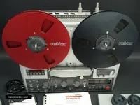
Oh and you know the RCA connection was designed by "RCA" of course, 50 or 60 years ago, to be used for short interconnections between a turntable and amplifier INSIDE of a phonograph. It was originally intended ONLY for short cable runs within the same piece of equipment. Being an unbalanced system it is susceptible to common-mode noise voltages. But it has become a standard in consumer audio
Think about this:
If a noise problem did occur, while you were recording the PERFECT vocal take by a performer after 20 takes, and you got it!
Now you realize the noise problem has ruined the quieter passages. If you had a balanced system, with balanced cords, you may have avoided the problem.
Not sure this thread will ever stay on track...

Credit to H. Ott, for what I plagiarized off him. Did I spell "plagiarized" right?
")

")