In theory, that's not a bad idea, but in practice it really doesn't make a difference. I've never seen a ground loop in a guitar that caused any problems.
That would be because "ground loop" is a misnomer. Every PCB-based electronic circuit in the world contains at least one looped ground around the perimeter of every board If a loop of grounds mattered, every device in the world would hum. If somebody tells you not to connect grounds between pots in a guitar, it is a pretty sure sign that he/she doesn't understand what causes ground-related hum, and that IMHO any other shielding advice from that person is suspect....

The so-called "ground loop" is really caused by two (generally AC-powered) devices having a shielded, unbalanced signal cable between them and one of the devices having a high resistance between its signal ground and the earth ground. As long as all the devices have a low resistance to ground, the vast majority of the signal flows out through the earth ground because that has lower resistance than flowing through the audio cable shield. If a device has a high resistance to earth, then any noise that device generates or otherwise picks up takes the new least-resistance path to ground through the audio cable shield into a device with a lower ground resistance, which ends up leaking into your signal as it passes through the shield.
It should be noted that you can only break the loop by either lifting the signal ground or lifting the earth mains ground on the device with the low resistance path to ground. If you lift the earth mains ground on the device with the high resistance path to ground, it won't do any good because the shortest path is still through the audio cable.
Well, a ground "loop" can also be caused by a few other things like leakage across high impedance (unbalanced) input transformers if the ground is poor, etc., but those are the sort of issues that would only get worse if you lifted a mains ground somewhere....
The point is that it isn't the loop that causes the problem. It is the device with a high resistance between the signal ground and the mains earth ground. The worst offenders are devices with no mains ground pin at all, including devices with wall wart power supplies and devices with two-prong power cords. If you have even one device that matches one one those descriptions, that's where a star grounding setup comes in handy.
Indeed, merely creating a secondary low resistance path between the devices (such as a 10 gauge wire connected between the grounds on an audio cable) often clears up the problem sufficiently because it creates a much lower resistance path to ground that doesn't flow through the audio cable. That said, it will generally work better if you feed this ground bus directly into the third grounding prong on a power cord.
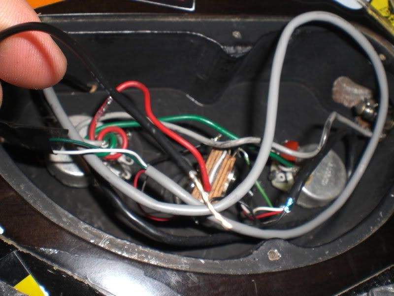
In the guitar case, the shielding is equivalent to the shielding on an audio cable. Adding grounds externally as a bypass would then make the sound imperceptibly better if the guitar were somehow producing hum... with the caveat that induction inside the guitar will be utterly dwarfed by induction between the shield and the signal conductor inside the guitar cable itself. Adding grounds internally as a bypass won't do much. About the only way it would make things worse is if you happened to run it parallel to a signal line (and closer than the shield), and even then, it is likely to be dwarfed by what's going on inside the guitar cable. And again, all that is predicated upon the guitar's shield and induction being the primary source of the hum, which it almost never is. The source is almost always the coils in the pickups, i.e. the hum is in the signal line to begin with, not in the shield. To the extent that hum is coming through the shield from the outside into the coils, however, lowering the resistance of the shield by adding grounding points can only be a good thing because it provides a better path to ground than traveling through the shield a greater distance to ground, thus reducing the amount of induction off the shielding material.


 That explains why some pedals cause noise.
 And the pickups can be shielded too.

