A
Adam P
Well-known member
I have a couple of questions regarding this schematic from Jensen Transformers here (.pdf file).
First, what is going on with the Black and White wires from the transformer?
Second, what purpose does the resistor and capacitor across the secondary side (I think that's what its called?) of the transformer serve?
Third, can a simple SPDT switch be introduced to modify this from a simple splitter into an A-B box?
Thanks a lot.
") Expensive little bugger at $70, but in this case you definitely get what you pay for. There is nothing as good out there as Jensens, as I see it.
Expensive little bugger at $70, but in this case you definitely get what you pay for. There is nothing as good out there as Jensens, as I see it.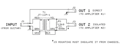

 :rolleyes:")