N
Neve1073lover
Inset French Saying Here
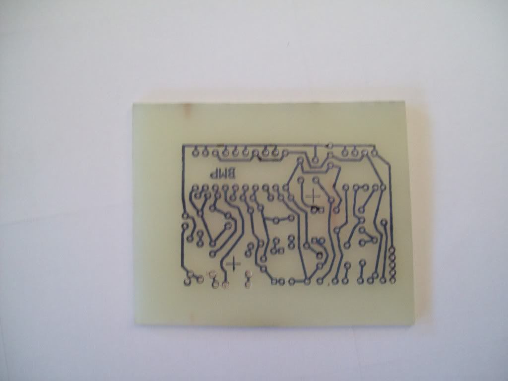
Latest Project. Fuzzzzzzzz
Design from generalguitargadgets.com.
Doing the 70's version:
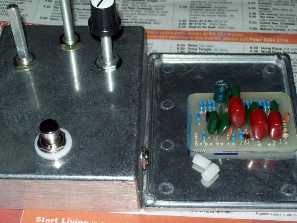
Son yet to have time to do anything but University so yet to test.
Need to add the LED (the spare wire...)
Design from generalguitargadgets.com.
Doing the 70's version:
Son yet to have time to do anything but University so yet to test.
Need to add the LED (the spare wire...)


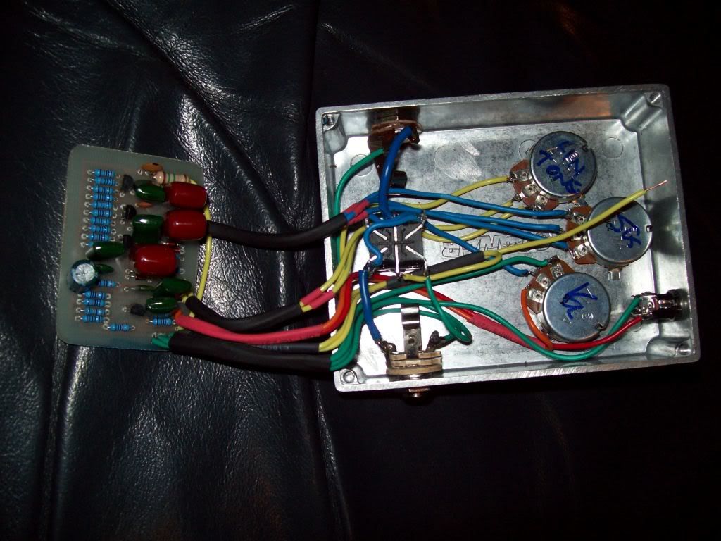
 Which transistors did you use there exactly?
")
")