Akai MG 1212 / 1214 needs repair

Fte

New member
Hello,

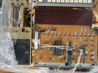
A while ago I picked an Akai MG1214 for cheap with great working mixer section, but unfortunatelly with some other part‘s flaws that need to be repaired.

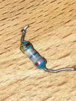
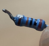
First thing I want to try is to fix is a loose resistor kind of thingy that was noodling around in the chassy (see picture below). However, the problem here is, so far I couldn‘t find it’s original location on one of the various pcb‘s. I have the service-manual and the schematics, but since I couldn’t figure out the resistor’s exact name/number/description, it’s rather impossible to find it. If anyone knows about this little thing, it’s name or about where it could possibly be located, I would be very happy. Thanks for any tips and hints:)

Best regards
Fte
 

Attachments

  • IMG_1085.jpeg
    IMG_1085.jpeg
    112.9 KB · Views: 7
Last edited:
I assume that is a part that fell into the works when repairs were being done, and is just that, a loose part. Sometimes stuff goes flying when you are trimming stuff out.
 
Yes, that’s what I thought, too. The problem is to find its original place again, and then solder it back in. I‘m afraid that, running the machine without this pice, may cause some damages.
 
I guess you could look for a 1% 1K resistor in the schematic. Looks like Brown Black Black Brown which would 1 0 0 with 10 multiplier and 1%? Hard to tell the colors from your picture. Might be Red Black Black Brown? Probably not. It would more likely be 2.2K which is a standard value, and the colors would be different.

1701882006767.jpeg

I'm with Sweetbeats. Somebody dropped a resistor and just left it in there. Soldered parts like that don't just fall out.
 
Last edited:
Hello Sweetbeats and TalismanRich,

Thanks for your suggestions. Thanks TalismanRich for the colour code schematic. Would it be ok then to just leave it like that, and simply run the machine? Or could that lead to damage if this thing would - opposed to our assumption - be an original unit’s part? I‘m not to deep familiar with electronics yet, unfortunatelly.

I will try to make another picture to define the rings.
 
Ok, here it is. To me it seems to be something like, Red Black Black Orange Brown (?)

Sorry for the blurry picture…
 

Attachments

  • IMG_0203.jpeg
    IMG_0203.jpeg
    803.1 KB · Views: 9
That would be a 200K resistor. Now you can look at the schematic and see if there are any in the circuit and then check them. Very pricey at $0.07 a pop!!! 😉


You can "calculate" the value of any resistor using this site.

 
  • Like
Reactions: Fte
Hey TalismanRich,

Thank you very much☺️
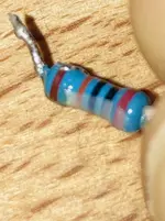
!! That helps aLot ok, I’ll go through the shematics. Do you know if there are also possible alternate names or synonymes I would have to look for, beside „200k“?
 
Last edited:
That part you’re holding was removed from something at some point. Look at the solder blob toward the brown tolerance band…and the angle of the tails…they would be at right angles if it melted itself out of the device. You would have bigger problems if it melted itself out of the PCB. You could probably still smell burnt electronics…the resistor body wouldn’t be blue anymore but rather scorched. That’s the kind of conditions that would cause a resistor to actually u weld from a fall out of a PCB. It just doesn’t happen and look like that. That there is a part somebody removed and replaced, sloppily I’ll say, and dropped in there, or it came from something else and dropped in by accident when it was opened up.
 
That part you’re holding was removed from something at some point. Look at the solder blob toward the brown tolerance band…and the angle of the tails…they would be at right angles if it melted itself out of the device. You would have bigger problems if it melted itself out of the PCB. You could probably still smell burnt electronics…the resistor body wouldn’t be blue anymore but rather scorched. That’s the kind of conditions that would cause a resistor to actually u weld from a fall out of a PCB. It just doesn’t happen and look like that. That there is a part somebody removed and replaced, sloppily I’ll say, and dropped in there, or it came from something else and dropped in by accident when it was opened up.
Hello SweetBeats, thanks for your suggestion☺️ The unit was definitely opened before, which I could see missing screws here and there. also some liquid must have been spilled into the faderslots, and underneath, some of the metal-housing rusted. If the resistor is just a left pice from something else, this would be good news. Some PCBs are really narrow side by side. Do you think it could also been caused by someone breaking or pulling the resistor out of its place, by accident?

Also I can see a strange cream-colored and hardened kind of coating around the resistor.
 

Attachments

  • IMG_0204.jpeg
    IMG_0204.jpeg
    2 MB · Views: 4
Last edited:
Dump question(sorry😅):
Could I also read the rings of the resistor the other way round? The calculator says, this would be 130 ohms then. How do I know from wich side I have to read them?
 
The PCB would break before the component could be forcibly removed. A solder joint is a metal weld. So if that’s what happened, there would be chunks of the PCB attached to the component.

I don’t know what the cream-colored something is…it could be the blue coating broken off by using pliers to remove the component along with the soldering iron…it could be RTV on the component used to temporarily hold it in place during wave soldering. Doesn’t matter. No offense…you’re over-thinking this. These are not the droids you’re looking for. Throw the resistor away. Not MG1214 but my MG1212 service manual, which is 140 pages, has 32 pages of service bulletins, modifications, component updates/changes…so that might be where it came from…tech was executing a field update, component launched into the bowels of the u it during removal, tech left it in there. Maybe something like that. Anyway, I guarantee you won’t find a vacant site for the component in the unit.
 
There is a slight separation of the tolerance band.

Sweetbeats is right. Turn the friggin' thing on. You can't just "pull out" a soldered resistor, and it's clearly not broken.

As for the service manual, it''s a royal pain in the ass when a manufacturer cross references a part number with a proprietary part number for something as generic as a resistor or capacitor.
 
Dump question(sorry😅):
Could I also read the rings of the resistor the other way round? The calculator says, this would be 130 ohms then. How do I know from wich side I have to read them?
There is typically a spacing gap between the multiplier band and the tolerance band, which you see between the orange and brown bands. That defines which one is the tolerance band and the last band. And anyway it wouldn’t be 130 ohms it would be a weird way of denoting a 2% 1 megaohm resistor…

Brown = 1
Orange = 4 (four zeros…so now we’re at 10000)
Black = one more zero

1,000,000 ohms. But that’s backwards.

It’s a 1% metal film 200K resistor.
 
Hey Guys, thank you very much both for your advice !!☺️☺️ and for clearing things up!
That‘s what I’ll be doing then, get it all together.
Yes, I also have the 1212 manual and can see, it would really have been a royal long trip😂
Thanks for the tip of tolerance band separation and how to correct reading the rings out, too.

I will reassemble the mixer side again, and now go for the tape-Section wich has some issues.
 
Last edited:
The mixer runs fine with some minor crackling on some knobs though. So far I tried to avoid contact-spray as much as I could (as I read it let’s the problem get worse over time).

My next step will be the tape-section. It has some flaws that seem to be very common issues with the 1212 and 1214. There is the The „idler-tire“ wich runs underneath the eject-mechanism. Mine has completely worn off into pieces. I want to place a new idler-tire over the little white plastic wheel that holds the tire. I have a spare-part. But I don’t know if I should use some glue for that in order to attach it, or, if I just put it on the wheel as it is…

Second, there is the „eject-slider“ (see pictures below) which manages the mechanisms to open and close the tape cartridge, and therefore stands under constant tension by springs. Mine, sadly torn into 3 pieces, plus a little bent in itself, due to years of tension I assume. Is there something I could do about it? I‘m not familiar with welding, and spare-parts are hard to get as it seems for now.
 

Attachments

  • IMG_0893.jpeg
    IMG_0893.jpeg
    3.9 MB · Views: 9
  • IMG_0828.jpeg
    IMG_0828.jpeg
    205 KB · Views: 7
Last edited:
Finally (for now) there is a little cable socket in the transport-PCB that is a little loose, you can move it around, but it’s not entirely off. Moore like a tooth that’s attempting to fall out soon. It’s the one that reads P25 on the attached pictures.
It’s left hand in the area where the transport buttons are. Do I have to re-solder it?
 

Attachments

  • IMG_0957.jpeg
    IMG_0957.jpeg
    1.8 MB · Views: 3
  • IMG_0955.jpeg
    IMG_0955.jpeg
    3.7 MB · Views: 3
Last edited:
Some of those parts can be hard to find. I suppose you could find a machine shop that could make you a eject mechanism bar.
 
A machine shop would probably be quite pricey to do a one off part like that. Perhaps you can search for places who scavenge parts from old dead machines, or hunt for dead units before they get tossed in the recycle bin. Many people don't bother fooling with old units like that once they break.
 
Hello RFR and TalismanRich,

Thanks for the suggestions, I will look for both opportunities nearby and meanwhile assemble the other stuff. In my area the Akai is very rare to find, and pricy as well. Also I had the idea of a 3D- scan and re-print of the slider, but I don‘t know if that’s a good idea.
 
Back
Top