6N3 'HiFi Buffer Preamp' = inexpensive tube preamp

  • Thread starter Thread starter Blue Jinn
  • Start date Start date
Blue Jinn

Blue Jinn

Rider of the ARPocalypse
I posted this thread at GDIY:

"6N3 HiFi Buffer Amp" -- what does it really do? Schematic corrected again

Start at post 14. I got a wrong schematic from a seller, which caused considerable confusion. The circuit has some quirks, like a 10k input Z and a 50k pot on the output. I stripped out the 10k resistors on the input, added a 1Meg on one channel, and made a straight cathode follower on the second. (This was before I realized the mistake in the schematic)

The Preamp is pretty straight forward two triode stages with negative feedback and about 15dB gain. With the 50k pot wide open (and which should/will be removed altogether) about 300 ohm output Z. It makes a decent DI for guitar on my M-520. The gain is plenty for the line ins. Note that the 6N3 can also be referred to has 6N3-J. This is apparently the Chinese version of the Soviet 6N3P. (Latin letters) Also, similar to 2C51. There is a 6N3 (USA?) that is a rectifier tube.

The cathode follower I made out of the other channel (wasting a triode stage in the process) is a good buffer for an old 12AX7 preamp I built in the last century. (Which has a very high output impedance)

Modding it is pretty easy. The 10k input resistors are SMD, but easy to remove, (but not so easy to replace with higher value ones) so I fashioned a 1/4" phone to RCA with the 1Meg across the phone jack.

You do need a power transformer with about 150v and 6.3v secondaries. I had some toroids built for a G7 project that are spec'd at 135v, but put out about 150v w/o load which worked fine for the B+ and I had a spare filament transformer as well. But if you include buying a PT you can get a decent tube pre (minus case) for about $US50.00-75 or so.

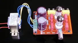
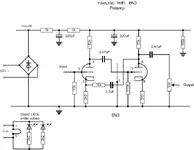
EDIT : Here are some pics from diyaudio: (The schematic redraw is also technically wrong, the two stages are actually two halves of two separate tubes, so the pin numbers are not correct) also, the top pic is a stock board, not modified. It's just to show the one I bought, (there are several different 6N3 buffer circuits floating around on Ebay.)
 

Attachments

  • 6N3-3.webp
    6N3-3.webp
    147.9 KB · Views: 2,514
  • YUANJING HiFi 6N3.webp
    YUANJING HiFi 6N3.webp
    14.3 KB · Views: 3,486
Last edited:
Nice work, Blue.
Have you built any of the Drip projects? I am contemplating the Drip Opto4, for one of those cold winter day projects.
 
Note, the pictures aren't of my mod, just two I culled from diyaudio, to show the board I used (there are at least three different buffer circuits floating around ebay that use a 6N3, one looks pretty similar to this one, but has a tube rectifier, and another one is a relatively low voltage cathode follower circuit.)

I have looked at the Drip site, and let's just say I've looked, looked again, looked at my wallet, looked again. Dreamed of having a fatter wallet,,,,

Check out groudiy though. I picked up a D-AOC board from Volker in Germany a while back. It is an optical compressor. I have not built yet, slowly gathering parts.

Also, check the white market. There are diy 1176 (several variants) LA-2A, with solid build threads, most of the Gyraf circuits are supported on groupdiy.
 
I hear what you are saying about your wallet... I am an advocate for my money, too.

Thanks for the input on the sites.
 
Nice one.
If I may? We live staurated in RF these days and that front end is wide open.

If you look at practically any guitar first stage you will see a grid stopper, nearly always 68k. This, in conjuction with the Miller input capacitance of the triode serves as a low pass filter with a turnover F of around 230kHz. The circuit shown has no stopper and the input capacitance will be very low due to the unbypassed cathode resistor.

Of course, most people, most of the time will not get a problem but a 1k series R and a 220pf shunt cap would be a good design addition IMHO.

Dave.
 
Thanks Dave. I'll keep that under advisement. I haven't had any RFI issues with this one, and that is completely wide open out side a chassis, but with the load resistor tied to the pins of a 1/4" jack, and basically an unbalanced cable (shield as ground) going to the RCA jack. I have had RFI (actually tuning in a radio station) with unshielded leads on a reverb tank though. That's a nice reverb, but it's on the bench for a re-wire. (PAIA HotSprings)

Note that the photos are "stock" not my actual modded board. I want to iterate though, that modded, this is a nice cheap way to get an actual real tube pre-amp, not a starved plate "tube effect" device. The input impedance is way way too low as designed, and the pot on the output is another IMO, flaw. But if you strip out the 10k input resistors, add a 1MOhm from input to ground, (and Dave's suggestion above a grid stopper and cap) and leave the 50k pot wide open, it makes a very nice DI unit., and you just control the volume from the board and/or your guitar.

I'm considering getting another one, putting a transformer in front of it, and trying it out as a mic pre.
 
S'right Blue!

With the long cold winter nights not far away, can I suggest a good book?

Merlin Blencowes' Designing Tube Preamplifiers for Guitar and Bass. Quite a lot of technicals and math but lots and lots of complete circuits with values etc.

Dave.
 
Thanks for the recommendation. The technicals are something I've lacked for a long time. Finally got my head around a plate curve at least in so far as calculating a plate and cathode resistor (I found a web page from a guy I assume lives in Indonesia based on his breakfast and lunch choices. It's written in smart-ass, which for some reason made more sense to me than the RCA guide....)
 
Hi guys!
First, greetings to all, since I am new to this forum.
I need good schematic or project for tube/valve buffer with 6n3 or 6922 for my CD-player Technicks.;):guitar:
thank you and cheers!:drunk:
 
That's a seriously bad circuit- I think the smart guys on diyaudio told you why. Before you go into any detail about the circuit problems at all, the volume pot on the output tells you that the "designer" doesn't even know the basics, he just slapped together a few stolen ideas, then stuck this abortion on EBay. No need to look further.

Blencoe's book (and his website) are excellent for instrument amps and tube basics. For hifi tube design, Morgan Jones is the place to go.
 
Agreed. Especially that 50k output pot. (Interestingly enough, the "McTube" and the 12AX7 preamp from a 1991 EM I built also has a fairly large pot on the output, which is why I wanted a buffer.) It is also telling that the schematic I was sent was all jacked up. I didn't bother to do any calculations on the cathode follower I built, (based initially on the inaccurate schematic) it works, but I have no idea where I'm running the tube. I have no idea where the tubes are running anywhere else either, and probably should go back and check that out.

I think you can modify it enough though and fairly easily to make it *usable* which still makes it damn cheap. I didn't get it for "hi-fi" at all, but as a simple guitar pre-amp. It does that fine, which makes it an easy and cheap way to go. Aside from the design quirks (like the 10k on the input) it seems to be fairly conventional.

CAVEAT: I'm a mere disciple here, so between the RCA Handbook and the ARRL book, I freely admit my reliance on GroupDIY gurus!
 
Last edited:
Anyone got a PCB design for this pre-amp ?
Eagle, Easy PC ?

this circuit is so simple it can be done point to point.

the grounded cathode amp does have its drawbacks, as all the power supply noise has a tendency to rest on the plate of the tube. negative feedback is used top inject the noise opposite in phase cancelling the noise.

The parts chosen are cheap but what do you expect.
the smt resistors should be advoided in tube design because they exibit poor emi rejection. The other resistors chosen have too much inductive characteristic. a non inductive wireround would be better (mills mra5's is what I use). The wima caps produce too much emi emmissions on tube equipment and should be only used in low voltage, low impedance settings a conenctric foil construction like in a solen poly or even a orange drop will have better performance. The coupling values are very arbitrary. I would use a 2.2uf solen bypassed with a .22uf paper in oil cap the .22 will counter any dual built up with using a large coupling and the phase response is more constant.

the input circuit should be balanced out so that what you're plugging into it doesn't cause excessive noise. disconnect the negative feedback, adjust the input resistor to the least noise, then reduce it slightly and add the resistance you removed in series with the grid to get the voltage back to 0V in the input. reconnect negative feedback.


also heaters should be on a DC supply in recording equipment to prevent the noise on the heater to modulate on the cathode. some people bark when I tell them to starve the heater a little. but what I've found out over the years is a 5V applied to a 6.3V heater will give me a gain that is constant over a longer period of time and the tubes last much longer providing that gain. the leds have a tendency to generate noise must be a fancy look thing.


the output potentiometer is a bad practice. its cheap, yes but the signal has to rely on how good the wiper is connect to the carbon disk. a better solution would be a rotary make before break switch configued as a ladder or "t" attenuator.
 
In response to ecca, you can get the whole thing on ebay, if you want to make changes, just desolder parts.

for drtechno, I haven't had any problem with noise, but I do plan to change heaters to DC anyway. (I am pretty sure there is DC bias applied to the heaters though.) The only other SMD resistors I can think of are the cathode and those led's, which are also the next to go. I also at some point should do a half assed frequency response.

I regret the kludged cathode follower "" I did, as I didn't bother to do any calculations. I eliminated the output pot entirely, prefering to control volume at the input, either at the guitar, or at the volume pot on the other pre, making this the "buffer" it is intended to be.

Everything I do is unbalanced.
 
Last edited:
for drtechno, I haven't had any problem with noise, but I do plan to change heaters to DC anyway. (I am pretty sure there is DC bias applied to the heaters though.) The only other SMD resistors I can think of are the cathode and those led's, which are also the next to go. I also at some point should do a half assed frequency response.

I regret the kludged cathode follower "" I did, as I didn't bother to do any calculations. I eliminated the output pot entirely, prefering to control volume at the input, either at the guitar, or at the volume pot on the other pre, making this the "buffer" it is intended to be.

Everything I do is unbalanced.

ok, Don't be hard on yourself bluejinn, if this your first time making stuff, great. I never got it down till after 3 years I started. and nuked a lot of stuff learning. But, as an old fart like me doing electronic stuff for 30+ years, its been a blessing of knowledge, the price I paid was I do not have good people skills. I'm sorry if I came off as dry and offensive. I am annoyed at the people that produce these boards on ebay because they sucker the enthusiest with a design that is limited in what it does, use weird parts, and not packaging it as a learning experience for the end user. They use parts that are marginal at best, but I guess Its good soldering exercise.
 
I will try to help you out on this situation. the first thing that will be the cheapest will be to get rid of those red square things. These have the wrong properties for high voltage because they have a tendancy to short out. there are two types of polypropolene caps, metallized (like these) and film and foil. for all tube designs I start with 1uf cap with a voltage rated above what my cold B+ voltage measurement (before the heaters warm up unless its tube rectified). The chinese tubes are most likely not made good. This particular tube was uncommon for audio and the ones that were like these that were ever in an audio circuit was a western electric design (thier tube number was 396A) raytheon 2c51 is the second choice.
 
These things are so damn cheap, that I'm tempted to get a few more to play around with. I do have a couple of bags of 600v poly caps ! in various "common" denominations. Didn't know that about Wima's as they seem to have a good rep otherwise in e.g. microphone circuits. As an aside, I actually find tube circuits easier, less moving parts and they are big enough that my soldering iron isn't going to screw up some CMOS IC... They also seem to be more "forgiving." I built something similar to the McTUbe about 20 years ago. When I bought hte power transformer, the guy at the electronics shop (which don't seem to really exist anymore, at least not where you can walk in and ask for a 250volt transformer...) talked me into using a 6X4 rectifier instead of silicon! So I did.

I hear what you are saying about Ebay sellers though. I'm not sure what is the target audience? I am able to go into this eyes open and know what it is, and where I can go for help to improve it.
 
the wima do have a good rep. its just people don't understand that metallized poly caps (caps with both metallized plates) start to magnetize under high dc voltage. this effects the capacitance. they do work well in electronics under 100V. that is why they are common in mics. (that and they're inexpensive and much more durable than a polystyrene (mechanically))

I'll think I said it before, the recommended poly caps are "film and foil" layered caps (partially metallized).


here are some examples:
Capacitor - 716P Series, Polypropylene Film, 400 V, .0047µF - .47µF | Antique Electronic Supply
Jupiter Red Astron Film Capacitors
Solen Fastcap: S3Q, S3ZG Teflon FEP Film & Tin Foil Cap
Solen Fastcap: SA, SB, SE, SM, SN, SY Series Polypropylene Film & Tin Foil Cap
Reliable PCU Capacitors

some are more pricey than others. some have precious metals and strict QC. but that is the real difference between a $500 amp and a $3000 amp.

also the resistors come into play. I like using the mills mra resistors and vishay z-foils.
the mills mra's in the cathodes and plates seem to bring the mids forward, like API gear forward ;)
 
getting boards for small signal stuff, I would try to find a board that has the standard EIA "9A" pinout so you can use audio grade tubes 12A*7's (au7, at7, ax7).
like this one:
Maratz 7 12AX7 3pcs 6Z4 Tube Preamplifier Kit WLX | eBay

and change out the blue caps and all the resistors.

maybe put one of these on the inputs (output +/- to inputs L and R, ground ct of sec.) :
https://www.edcorusa.com/p/114/mxl10cs
outputs L and R to pins 2&3 xlr. then there will be a mic pre born.

just some more ideas for ya..
 
Back
Top