Blue Jinn
Rider of the ARPocalypse
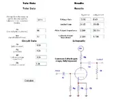
Well, this was inspired by another thread I started, and this is my first attempt at actually designing something from scratch. Used the calculator found here:
http://amps.zugster.net/tools/triode-calculator
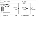
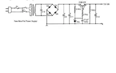
and the duncan amps power supply calculator. PSU is inspired by the PRR Varimu psu, which uses the second primary of a dual primary transformer for the B+ supply. Being totally a newbie at this, I based the heater around the constant current model (.3A for the heater) and used what I thought was the total resistance of the tube load being the plate resistor and the follow on stage in parallel (?) for the B+ supply. I assumed the load to be 160k, based on driving a 10k impedance balanced input, (10k reflected back though a 1:4 transformer) which is where I got the 62k load for the B+ psu model. (100k || 160k)
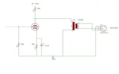
I eliminated the output coupling cap as this is transformer coupled. Note that everything I have is pin 3 hot, so I re-inverted the phase by swapping the terminals on the transformer output (which I thought I read about somewhere else)
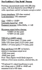
The gain is supposed to be right around 16 per the calculator listed above, and so the 4:1 transformer knocks that down to 4x or about 12dB, and should lower the impedance to around 250 ohms or so, again based on the output impedance from the triode calculator of about 4k. The zugster.net calculator differs somewhat from the datasheet for teh tube itself. B+ was chosen as a swag based on the 120v transformer. The plate resistor and cathode resistor were more or less from the datasheet and teh calculator kinda a compromise between teh two. I have yet to actually learn how to read a plate curve so I'm basing all this on the what I've gleaned from various websites.
One thing, not sure how necessary it is to have the input coupling cap, I've seen it omitted in some circuits, and not sure why it would be needed except as a precaution. If so seems .1uF is a pretty standard value.
Also, I had thought also of using this as part of the PRR, which has a regulated B+ of 100v. So B+ here is 100-150v.
I picked the 6111 because I thought a submini tube would require slightly less parts, (tube socket) the 6111 is pretty cheap, and the whole thing less transformers could be built on one or two of those radio shack terminal/perf boards. Sonically, I'm not sure how well the 6111 does, I've seen it used in a lot of guitar circuits which weren't intended to sound clean.
Here it is:
http://amps.zugster.net/tools/triode-calculator
and the duncan amps power supply calculator. PSU is inspired by the PRR Varimu psu, which uses the second primary of a dual primary transformer for the B+ supply. Being totally a newbie at this, I based the heater around the constant current model (.3A for the heater) and used what I thought was the total resistance of the tube load being the plate resistor and the follow on stage in parallel (?) for the B+ supply. I assumed the load to be 160k, based on driving a 10k impedance balanced input, (10k reflected back though a 1:4 transformer) which is where I got the 62k load for the B+ psu model. (100k || 160k)
I eliminated the output coupling cap as this is transformer coupled. Note that everything I have is pin 3 hot, so I re-inverted the phase by swapping the terminals on the transformer output (which I thought I read about somewhere else)
The gain is supposed to be right around 16 per the calculator listed above, and so the 4:1 transformer knocks that down to 4x or about 12dB, and should lower the impedance to around 250 ohms or so, again based on the output impedance from the triode calculator of about 4k. The zugster.net calculator differs somewhat from the datasheet for teh tube itself. B+ was chosen as a swag based on the 120v transformer. The plate resistor and cathode resistor were more or less from the datasheet and teh calculator kinda a compromise between teh two. I have yet to actually learn how to read a plate curve so I'm basing all this on the what I've gleaned from various websites.
One thing, not sure how necessary it is to have the input coupling cap, I've seen it omitted in some circuits, and not sure why it would be needed except as a precaution. If so seems .1uF is a pretty standard value.
Also, I had thought also of using this as part of the PRR, which has a regulated B+ of 100v. So B+ here is 100-150v.
I picked the 6111 because I thought a submini tube would require slightly less parts, (tube socket) the 6111 is pretty cheap, and the whole thing less transformers could be built on one or two of those radio shack terminal/perf boards. Sonically, I'm not sure how well the 6111 does, I've seen it used in a lot of guitar circuits which weren't intended to sound clean.
Here it is: