Blue Jinn
Rider of the ARPocalypse
The uploader I've determined is completely arbitrary. E.g. upload the 2001 schematic = fail. Save as a GIF, OK. Whatever


 Now I can't manipulate the order of the pictures.... OK, here goes again:
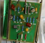
Unmodded board:

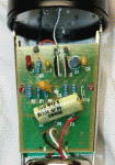
Modded board:
Note, I didn't route the transformer wires the original way. Also, lifted a solder pad while undoing the stock transformer, (brute force desoldering iron...) so had to move the new one to a new place. Once you've removed the pnp follower section, there are a lot of free spots to solder. R7 is the second resistor in from the right. R6 and R7 form a voltage divider for the FET. There is a thread on Groupdiy regarding the Aurycle FET mics (same circuit) and installing a trimmer at R6. I'm going to look into doing that, as I replace the FET next.

The new transformer is a little too big for the bell housing, which is basically flapping in the breeze at the moment. I used the same ones on a Royer I did, which required some drilling to the base of the mic to make it fit, (basicallly just making four notches for the transformer.) The Cinemag will fit, and I'm tempted to get one, but going to see the impact a new FET has first.
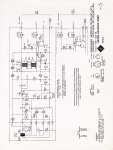
The original 2001 schematic

The u87 View attachment 72747View attachment 72747-which won't upload with the WYSIWIG editor: even though it's a jpeg....

Except this version will.
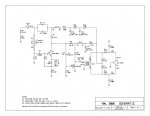
OK and the pdf of the front end mod.


 Now I can't manipulate the order of the pictures.... OK, here goes again:
 Unmodded board:

Modded board:
Note, I didn't route the transformer wires the original way. Also, lifted a solder pad while undoing the stock transformer, (brute force desoldering iron...) so had to move the new one to a new place. Once you've removed the pnp follower section, there are a lot of free spots to solder. R7 is the second resistor in from the right. R6 and R7 form a voltage divider for the FET. There is a thread on Groupdiy regarding the Aurycle FET mics (same circuit) and installing a trimmer at R6. I'm going to look into doing that, as I replace the FET next.

The new transformer is a little too big for the bell housing, which is basically flapping in the breeze at the moment. I used the same ones on a Royer I did, which required some drilling to the base of the mic to make it fit, (basicallly just making four notches for the transformer.) The Cinemag will fit, and I'm tempted to get one, but going to see the impact a new FET has first.
The original 2001 schematic

The u87 View attachment 72747View attachment 72747-which won't upload with the WYSIWIG editor: even though it's a jpeg....

Except this version will.
OK and the pdf of the front end mod.
Attachments
Last edited:
