B
You are using an out of date browser. It may not display this or other websites correctly.
You should upgrade or use an alternative browser.
You should upgrade or use an alternative browser.
sweetbeats
Reel deep thoughts...
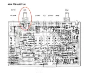
It is R421 on the MONITOR PCB. It is a 20K A-taper pot with two elements in tandem…so it is marked “20KAX2”.
But before you go further, what is the specific problem you are having? I ask because the pot is fed by 4000 series logic (an LC4966) and there is a pattern of those going bad in a number of period Teac devices. I think this is because, and this is one of the very few issues like this in a Teac device where I’m, like, “well *that* wasn’t the best idea…”, they powered the device using the +/-15V rails, and the device has a max 30V peak-to-peak input power rating. Now, there are usually dropping resistors on the power rails of each PCB in this era of Teac stuff…like usually 33R or something, which drops the power a little bit…not a lot, but a little is better than none when you’re powering an active device at its input capacity, but I don’t even see those on the MONITOR PCB…I see them on the INPUT PCBs…22R there…but nothing on the MONITOR PCB. So that LC4966 is running right at capacity all these decades. So what’s going on with your headphone output?
But before you go further, what is the specific problem you are having? I ask because the pot is fed by 4000 series logic (an LC4966) and there is a pattern of those going bad in a number of period Teac devices. I think this is because, and this is one of the very few issues like this in a Teac device where I’m, like, “well *that* wasn’t the best idea…”, they powered the device using the +/-15V rails, and the device has a max 30V peak-to-peak input power rating. Now, there are usually dropping resistors on the power rails of each PCB in this era of Teac stuff…like usually 33R or something, which drops the power a little bit…not a lot, but a little is better than none when you’re powering an active device at its input capacity, but I don’t even see those on the MONITOR PCB…I see them on the INPUT PCBs…22R there…but nothing on the MONITOR PCB. So that LC4966 is running right at capacity all these decades. So what’s going on with your headphone output?
B
Basilharewood
New member
I only get signal to the left headphone unless I push the monitor knob down and then I get a signal to both left and right.It is R421 on the MONITOR PCB. It is a 20K A-taper pot with two elements in tandem…so it is marked “20KAX2”.
But before you go further, what is the specific problem you are having? I ask because the pot is fed by 4000 series logic (an LC4966) and there is a pattern of those going bad in a number of period Teac devices. I think this is because, and this is one of the very few issues like this in a Teac device where I’m, like, “well *that* wasn’t the best idea…”, they powered the device using the +/-15V rails, and the device has a max 30V peak-to-peak input power rating. Now, there are usually dropping resistors on the power rails of each PCB in this era of Teac stuff…like usually 33R or something, which drops the power a little bit…not a lot, but a little is better than none when you’re powering an active device at its input capacity, but I don’t even see those on the MONITOR PCB…I see them on the INPUT PCBs…22R there…but nothing on the MONITOR PCB. So that LC4966 is running right at capacity all these decades. So what’s going on with your headphone output?
I forgot about this and remember now when I used it to record when I had everything set up previously I use to tape it down to record anything that required being mic’ed up.
sweetbeats
Reel deep thoughts...
The pot is mounted to the PCB. My hunch is you just need to re-flow the solder joints. It probably got bumped at some point and cracked a solder joint.
B
Basilharewood
New member
What do you mean by re-flow the solder joints? I’m not familiar with electronics
Last edited:
sweetbeats
Reel deep thoughts...
Take a soldering iron and heat up each of the solder joints to melt the solder and essentially re-do the welds.
B
Basilharewood
New member
ok makes sense, and should be achievable with my lack of soldering skills, thanks sweetbeats
sweetbeats
Reel deep thoughts...
It’s helps to add just a little solder when you do it.
B
Basilharewood
New member
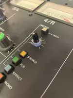
Hi @sweetbeats just circling back to this as I opened up the mixer to take a look again at this headphone monitor issue (just plays out of one headphone, but works with both when I press it down) I re-soldered the connections to the board for the R421 monitor pot but it still does the same thing, tbh the solder joints looked fine and nothing was loose on there. What I did notice is that the actual plastic part of the knob moves up and down within the metal chassis when I press it, which doesn't happen for any of the other knobs on the board, which must be the reason for the lack of connection to feed both L/R signals through to the headphones. Have you ever come across this before?
Attachments
sweetbeats
Reel deep thoughts...
Refresh my memory…works when you press what down?Hi @sweetbeats just circling back to this as I opened up the mixer to take a look again at this headphone monitor issue (just plays out of one headphone, but works with both when I press it down) I re-soldered the connections to the board for the R421 monitor pot but it still does the same thing, tbh the solder joints looked fine and nothing was loose on there. What I did notice is that the actual plastic part of the knob moves up and down within the metal chassis when I press it, which doesn't happen for any of the other knobs on the board, which must be the reason for the lack of connection to feed both L/R signals through to the headphones. Have you ever come across this before?
How much does the pot shaft deflect approximately?
B
Basilharewood
New member
When I press down the knob itself. The plastic shaft moves about 1mm max 2.Refresh my memory…works when you press what down?
How much does the pot shaft deflect approximately?
B
Basilharewood
New member
When I press down the knob itself. The plastic shaft moves about 1mm max 2.
Unfortunately there no replacement parts for this pcb anywhere online so a fix (if possible) is only solution. Can i remove the shaft part from the metal holder and potentially try repair something under here, or is that a terrible idea?Refresh my memory…works when you press what down?
How much does the pot shaft deflect approximately?
Attachments
sweetbeats
Reel deep thoughts...
You can replacements for that part. You’re just not going to find by searching for M-208 headphone pot. You have to search by the specs for the pot which is a dual element 20K ohm A-taper pot with a 1/4” ‘D’ shaft. You’ll find this abbreviated as “20KAX2”. You’ll also want to measure the shaft length. So then you go to Mouser or Digikey and search for pots with those specs and look at the data sheets to verify the pin configuration. I know some or all of that may be unfamiliar to you, but my point is it’s not a matter of the pot not being available, you’re just not going. To find it searching by make, model and function.
And sure you can try to take it apart, bend those tabs you see on the top over and see if you can remove the top to access the inside. I don’t know how easy that will be depending on how it’s constructed…I think there is one element with two tracks, so that will be easier to disassemble vans pot with two separate stacked elements with one track each…I have to look at the PCB layout to see the pin layout…okay yeah I think it’s a single element so you can try just bending those tabs over and pull the top off and see if you can see what’s going on in there. It’s normal for there to be okay in the shaft, especially on plastic shaft pots, but it may just be you need to gently deflect on of the wipers so it makes better contact with the element.
And sure you can try to take it apart, bend those tabs you see on the top over and see if you can remove the top to access the inside. I don’t know how easy that will be depending on how it’s constructed…I think there is one element with two tracks, so that will be easier to disassemble vans pot with two separate stacked elements with one track each…I have to look at the PCB layout to see the pin layout…okay yeah I think it’s a single element so you can try just bending those tabs over and pull the top off and see if you can see what’s going on in there. It’s normal for there to be okay in the shaft, especially on plastic shaft pots, but it may just be you need to gently deflect on of the wipers so it makes better contact with the element.
B
Basilharewood
New member
Ok sure, thanks. I did try and source an original replacement from tascam ninja but he has sold out of that PCB and said other people are also waiting, he did mention someone he spoke to managed to replace it with a newer part but that someone didn't say what with. Been looking through Mouser and Digikey but not sure any of their listed 20K potentiometers seem to look like a suitable replacement, I'm sure with some know-how one of them that is close enough could be adapted to fit/work but that is above my skillset. I guess I'll just have to live with it for now and wait for a replacement PCB to show up or a 200 series mixer for spares and parts to come on the market. Thanks again @sweetbeats
sweetbeats
Reel deep thoughts...
If you were just going to wait for a complete replacement assembly to materialize anyway, why did you ask about a replacement pot or repairing what’s there? I’m left wondering why I took my time to study the schematic, parts list and PCB layout to let you know you likely can get a replacement pot, but more importantly you asked about opening the pot up and I told you it looks like you can do that and likely just need to adjust the position of one of the wipers. But your response is “okay I guess I’ll just have to wait for a complete replacement PCB assembly”? I don’t get it.
B
Basilharewood
New member
I do not want to wait for a replacement assembly, i want to fix it now but with my lack of knowledge doesn’t seem likely. I appreciate your response i really do, but finding a new part that fits the specs with limited knowledge is a big ask. I tried but it didnt seem obvious to me, i have however contacted mouser with the info i have and what I’m trying to replace so hopefully they can direct me to a part that will work. But again even if that happens I’ll have to wing trying to insert said part with limited knowledge. In terms of removing the current pot from its housing again I tried but it felt like i was about to break something trying to get it out, so came to the sad realisation that waiting for a replacement PCB is probably the safest most successful way I can get this mixer fully functional.
Last edited:
sweetbeats
Reel deep thoughts...
Where are you located in the world? By the spelling of the word “realisation” I’m guessing you’re on the other side of the “pond” from the United States…
B
Basilharewood
New member
I'm in the UK yeah. This whole process is mad stressful for me not going to lie, eg. I've just put the mixer back together and now there's something up with the VU meters... channel 2 needle is not responding and neither is channel 3's unless I press down "meter 3/4/mon" button on the master out section in which case 3 works. I must have knocked something or disconnected something putting it back together. Every time I open it up it's a massive gamble for me, I'm a musician who just wants the gear I own to work properly.
sweetbeats
Reel deep thoughts...
Bummer you’re so far away I was going to say pull the boards (there are two of them siamesed together with the monitor select switches sandwiched between them) and send them to me and I’ll repair it.
“I’m a musician who just wants the gear I own to work properly.”
To which I respond:
“And this is why we don’t have nice things.”
lol…not trying to make fun but that idiom just popped into my head immediately when I read that last sentence of your last post. I can relate and even empathize. I think the reality is, in the realm of vintage equipment, and progressively so as that equipment ages, you either have a good reliable tech at your disposal, or learn how to troubleshoot, diagnose, repair and maintain said vintage equipment, acquiring the necessary tools and diagnostic equipment in the process, -OR- acquire more reliable equipment. Those are your choices because there are **always** issues to varying degrees with which to contend with this bracket of vintage equipment. My Studer console circa 2000 is, relatively speaking, very trouble free, but it also was a high-bracket console in its day and you get what you pay for in terms of performance and reliability. But in the more “budget” bracket (and that’s not meant to be a judgmental statement…the lower cost arena was Tascam’s target with their consoles like the M-200 series) it’s not possible to have all your cake and eat all of it too. In the 1980s, in particular with their Tascam analog audio production equipment, Teac generally did a great job of innovating and incorporating unique and usable feature sets into their products compared to their competitors, and doing so without implementing what I’ll call stupid value-engineering decisions. Sure there was necessary value engineering to meet their objectives, but they were pretty smart about it. But there are still age-related reliability issues stemming from things like the quality of the pots and switches (which were good for the price bracket, and better than many and certainly better than what you’ll find in more contemporary “budget” consoles!), the type of board-to-board and board-to-cable connections (tin-plated steel) as well as issues stemming from the use of phenolic resin PCBs (also very common), so it is what it is. But if you want to use a console like the M-208, and you want it to be dead-nuts fully-operational as much as possible, you have to understand this reality that it will have issues from time to time, and as you are experiencing, every time you open it up and do *anything* you increase the risk of something else going awry. So you either have to be personally prepared to rectify the driving issue and the secondary issue that arises when you crack it open (or tertiary issue, etc.), or have somebody available to do that for you, or replace it with something more reliable, though that understandably comes with compromises either in cost or features or whatever…no free lunches.
Some of us, who are also musicians first, want reliable and tip-top performance so bad, but also have a strong desire to have very specific vintage gear AND know how to fix it themselves they spend years and years…decades even, studying, learning, finding kind people from whom to learn and receive assistance, diving into project after project scalp-deep, and making LOTS of mistakes in order to learn until they can fix most anything that happens with the range of equipment in their fleet. And that essentially describes me. That is the crux of why I deviated at all from a focus on playing and recording was to just learn how to maintain and repair and/or upgrade anything I use. And that bred a curiosity about how different manufactures design their circuits and engineer their product designs, which, along with a journey to find the equipment that best suits me, led to a LOT of different devices coming and going, sometimes just to satisfy the simple curiosity of cracking it open and looking inside. When I started down this path of learning I barely knew the business end of a soldering iron, and certainly couldn’t understand it find my way around any kind of electrical schematic. That’s different today, but of course the deviation comes at a cost too. No free lunches. Our resources both in time and money are always limited.
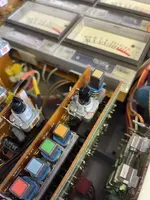
As to your meter problem, there’s that “mother” PCB that goes across the bottom of the PCBs in the master section. Those connections are notorious for getting oxidized or developing cracked solder joints. You could try gently manipulating those connections where they plug into the MONITOR PCB A & B boards…the one with the monitor level pot and meter source select switch on it, and then there’s the one right next to it to which the other side of the switches are mounted. On the second board the black two pin connector is what goes to the meters. Exercise that. Look for compromised solder joints where the pins of the connector on the board solder to the board. And then where both of those boards connect to the mother PCB. It’s also possible this set of connections where the MONITOR PCB array connect to the MOTHER PCB is the cause of your headphone issue. Run some audio to the headphones and listen while gently manipulating the connections of the MONITOR PCBs to the MOTHER PCB. If you get intermittent signal in both sides of the headphones and also look at the meter performance…if you can get intermittent performance in the meters by gently manipulating the MOTHER PCB connections you may just need to carefully re-seat the MOTHER PCB, or it may need solder joints re-flowed, but it’s totally fixable. It’s also possible the U405 needs replaced for the headphone issue, but I suspect that’s not the case. But those 4000 series logic chips are known to go bad in a number of period Teac products because they chose to power the circuit at the maximum level the chips can handle, which shortens their service life.
“I’m a musician who just wants the gear I own to work properly.”
To which I respond:
“And this is why we don’t have nice things.”
lol…not trying to make fun but that idiom just popped into my head immediately when I read that last sentence of your last post. I can relate and even empathize. I think the reality is, in the realm of vintage equipment, and progressively so as that equipment ages, you either have a good reliable tech at your disposal, or learn how to troubleshoot, diagnose, repair and maintain said vintage equipment, acquiring the necessary tools and diagnostic equipment in the process, -OR- acquire more reliable equipment. Those are your choices because there are **always** issues to varying degrees with which to contend with this bracket of vintage equipment. My Studer console circa 2000 is, relatively speaking, very trouble free, but it also was a high-bracket console in its day and you get what you pay for in terms of performance and reliability. But in the more “budget” bracket (and that’s not meant to be a judgmental statement…the lower cost arena was Tascam’s target with their consoles like the M-200 series) it’s not possible to have all your cake and eat all of it too. In the 1980s, in particular with their Tascam analog audio production equipment, Teac generally did a great job of innovating and incorporating unique and usable feature sets into their products compared to their competitors, and doing so without implementing what I’ll call stupid value-engineering decisions. Sure there was necessary value engineering to meet their objectives, but they were pretty smart about it. But there are still age-related reliability issues stemming from things like the quality of the pots and switches (which were good for the price bracket, and better than many and certainly better than what you’ll find in more contemporary “budget” consoles!), the type of board-to-board and board-to-cable connections (tin-plated steel) as well as issues stemming from the use of phenolic resin PCBs (also very common), so it is what it is. But if you want to use a console like the M-208, and you want it to be dead-nuts fully-operational as much as possible, you have to understand this reality that it will have issues from time to time, and as you are experiencing, every time you open it up and do *anything* you increase the risk of something else going awry. So you either have to be personally prepared to rectify the driving issue and the secondary issue that arises when you crack it open (or tertiary issue, etc.), or have somebody available to do that for you, or replace it with something more reliable, though that understandably comes with compromises either in cost or features or whatever…no free lunches.
Some of us, who are also musicians first, want reliable and tip-top performance so bad, but also have a strong desire to have very specific vintage gear AND know how to fix it themselves they spend years and years…decades even, studying, learning, finding kind people from whom to learn and receive assistance, diving into project after project scalp-deep, and making LOTS of mistakes in order to learn until they can fix most anything that happens with the range of equipment in their fleet. And that essentially describes me. That is the crux of why I deviated at all from a focus on playing and recording was to just learn how to maintain and repair and/or upgrade anything I use. And that bred a curiosity about how different manufactures design their circuits and engineer their product designs, which, along with a journey to find the equipment that best suits me, led to a LOT of different devices coming and going, sometimes just to satisfy the simple curiosity of cracking it open and looking inside. When I started down this path of learning I barely knew the business end of a soldering iron, and certainly couldn’t understand it find my way around any kind of electrical schematic. That’s different today, but of course the deviation comes at a cost too. No free lunches. Our resources both in time and money are always limited.
As to your meter problem, there’s that “mother” PCB that goes across the bottom of the PCBs in the master section. Those connections are notorious for getting oxidized or developing cracked solder joints. You could try gently manipulating those connections where they plug into the MONITOR PCB A & B boards…the one with the monitor level pot and meter source select switch on it, and then there’s the one right next to it to which the other side of the switches are mounted. On the second board the black two pin connector is what goes to the meters. Exercise that. Look for compromised solder joints where the pins of the connector on the board solder to the board. And then where both of those boards connect to the mother PCB. It’s also possible this set of connections where the MONITOR PCB array connect to the MOTHER PCB is the cause of your headphone issue. Run some audio to the headphones and listen while gently manipulating the connections of the MONITOR PCBs to the MOTHER PCB. If you get intermittent signal in both sides of the headphones and also look at the meter performance…if you can get intermittent performance in the meters by gently manipulating the MOTHER PCB connections you may just need to carefully re-seat the MOTHER PCB, or it may need solder joints re-flowed, but it’s totally fixable. It’s also possible the U405 needs replaced for the headphone issue, but I suspect that’s not the case. But those 4000 series logic chips are known to go bad in a number of period Teac products because they chose to power the circuit at the maximum level the chips can handle, which shortens their service life.
B
Basilharewood
New member
Dude, that's super nice of you and yes, haha hear this message loud and clear. I'd like to think I'm on the same path of studying and learning and one day be able to maintain the equipment I like to use, which as it stands is analogue equipment and if at any point I can afford to upgrade from this budget line to more reliable equipment, I'll be 100% jumping on that. A lot of this is out of financial necessity for me atm, also trying to fix it rather than seek help as 1. analogue audio engineers are a rare breed here in the UK 2. more expensive than the equipment I'm currently using and 3. like I said I want to learn how to maintain and repair this imo beautiful equipment for myself. I really do appreciate people like yourself on here passing on the baton so to speak and sharing your experience and knowledge. And in good news, I've just opened the mixer up again and made sure everything was connected properly and thankfully everything (minus the dodgy monitor pot) seems to be working properly again, not entirely sure what was loose or not connected. I have read through your troubleshooting message anyway and I am soaking all of this terminology in as to better understand and use for any future issues that may arise. I think a basics in electronics course is next on my agenda