Define "phase"? Or is it polarity?

.guitar

New member
I know a lot about digital audio and the theory behind it, but I'm not quite sure what phase is? Or polarity? I know they are different but most audio editors call polarity "phase"?

For example, recording a stereo guitar track with 2 mics...if you invert the "phase" on one, it produces a really strange sound...almost like you can't tell where the guitar is coming from...:confused:

I'm wondering if there is a way to gradually go from normal "phase" all the way to inverted using automation, or if it is something that can only be flipped completely...or if there is another method to get that effect.

It's probably a stupid question, but considering I'm not exactly sure what it even is..........

Thanks.
- danny.guitar
 
from my perspective it's all a matter of degrees... in the case of a flip or 180 out.. thats really polarity... but there's things like caps that can affect the phase in different degrees and at different frequencies... that's how a passive crossover works... and EQ's too...
 
Polarity inversion is exactly what the name suggests, it is a change of electrical polarity; what was a negative voltage is now a positive voltage, and vice versa.
Mathematically and simply put it's

V2 = V1 * -1

where V2 is the voltage after inversion and V1 is the original voltage. In other words, simply take the voltage value at every point in the waveform and multiply it by -1 to get the inverted voltage value.

Phase is a bit more complicated in that, like an angle, it can have a value of anywhere from 1° to 360° (or 0°). This is why the change in phase value is commonly referred to as "phase angle". The math involved includes square roots of tangents and stuff like that, which is probably beyond what's wanted here.

But to simplify for this discission, a "phase inversion" is basically an instantaneous (no time shift) phase change of 180°. This resembles a polarity inversion in that an instantaneous 180° phase change does invert the direction up or down of the wave rests, but there is a technical difference:

A polarity inversion, by definition, inverts or flips the wave around the horizontal axis of 0 volts DC. A phase inversion inverts or flips the wave around whatever the rest voltage of the signal may be (the rest voltage being whatever the DC voltage may be during silence.) Put mathematically, phase inversion can be represented by

V2 = (V1 * -1) + VDC

So you can see that if the rest voltage VDC happens to equal 0 (no DC offset), that phase inversion and polarity inversion will have the same result and will appear to be the same thing. But add any DC offset, and the results will be different by the amount of DC offset in the signal.

As far as automating inversion, most DAW editors have an "Invert" option available somewhere in them. As to whether any of them allow you to to that only to part of the signal (e.g. just a highlighted part), I'm not sure; it's usually a function run on the whole track. And as far as automating phase changes dynamically, I don't know offhand of any plugs that do that, but maybe someone else might.

G.
 
I have the answer! (I use this title alot)

Phase is the time relationship of two copies of a signal.
example:
1. You duplicate a track in protools
2. slide one of them 20ms to the right.

Now there is a phase difference.

Polarity is which direction the signal goes first. (this is a crappy definition but I can't think of a better one)
example:
1. You duplicate a track in protools again
2. You flip the polarity

Now whenever the waveform in track1 is going up, the waveform in track 2 is going down.

So If you pan them both center, and set them to the same volume, they'll cancel out and you won't hear anything. (Or in real life, there are small rounding errors and it's just very very quiet).

More...
The relationship between 180 out of phase and a polarity flip is this:

If you have a sine wave, and you make a copy of it like above, and the flip the polarity of one, it cancels out.

If you take the same sine wave and move it just far enough out of phase that it looks like it's a polarity flip (one goes down while the other goes up) it also cancels out.

The reason they aren't the same is because with real audio there are overtones. So when you flip the polarity it cancels fully.

But when you change the phase, some frequencies cancel, and some reinforce, depending on the delay time.

Hope this helps... I'll probably convert this answer to a blog post sooner or later :)
 
Phase is the time relationship of two copies of a signal.
Not necessarily. It is possible to effect phase change in zero time simply by manipulating the voltage based upon the calculations for phase angle change without incorporating any time change.

Also, for a complex waveform, shifting the waveform in time will change the phase angle differently for each frequency involved. It is impossible, for example, to phase invert a complex waveform via a time shift. However, by using actual phase change calculation without the time shift, one can effect a 180° - or any other degree, FTM - phase change to the entire waveform across all frequencies.

G.
 
phase?

Also, for a complex waveform, shifting the waveform in time will change the phase angle differently for each frequency involved. It is impossible, for example, to phase invert a complex waveform via a time shift. However, by using actual phase change calculation without the time shift, one can effect a 180° - or any other degree, FTM - phase change to the entire waveform across all frequencies.

G.

If you apply a phase change of 90 degrees to the entire waveform across all frequencies, doesn't that just result in an amplitude reduction? something like 6db?

Maybe you mean instantaneous phase?
 
Last edited:
a Helpful image

This is probably also helpful for understanding phase:
Phase_shift.png


From: wikipedia
 
Last edited:
This is probably also helpful for understanding phase:
Phase_shift.png


From: wikipedia
Note that that graph is showing a phase change in zero time; both waveforms start at the same time, there is no horizontal shift. The shift is, in fact one of voltage (vertical measure). They really should be drawing it like the first attachment, below (the one with the green legend).

If you want to introduce a time shift, then Wikiality has drawn it slightly wrong, it should be like the second attachment below.

The problem with looking at phase change as a time shift is that it only works for simple waveforms like pure sine waves, like we're showing here, and even then only for the amount of time in which both waveforms overlap.

But move to the the real world of sound with complex non-sinusoidal waveforms consisting of several modulating frequencies and we have a problem because a shift in time will cause a different phase angle change for every different frequency. Remember, frequency is time-based also, measured in wave cycles per second A delay of 1/1000th a second will mean a 360° cycle rotation at 1kHz, but at 250Hz it's only a 90° rotation. At 500Hz it's a 180° rotation. and so forth.

Now throw pink noise in the time line and no matter what your amount of time shift, you have a virtually infinite combination of phase rotations all happening at once.

There is no way to invert a complex (non-sinusoidal) wave through simple time shift. One does not simply factor a multiple of 2pi radians out of the time shift. In fact, there is no way to change the phase angle of a complex wave by any set number of degrees through a time shift. Therefore, phase is not a simple time-based phenomenon for real-world audio signals.

The only way to change a complex (non-sinusoidal) waveform by a set phase angle (including "phase inversion") is to remove the factor of time from the equation altogether, leave the waveforms in place and perform a phase change of 180° in place.

As long as you're in Wikiality, look up Fourier and Hilbert transform functions. These nasty beasts will start to point you in the right direction, but frankly they make my head hurt and are a bit too much for this forum I think.

G.
 

Attachments

  • Phase_shift_0time.jpg
    Phase_shift_0time.jpg
    20.7 KB · Views: 163
  • Phase_shift_horiz.jpg
    Phase_shift_horiz.jpg
    21.7 KB · Views: 162
Last edited:
That graph is a sin/cos function and is not phase shifting.
Well, to be fair, cosine is sine with a phase shift of pi/2 (cos(x) = sin(x + pi/2)).

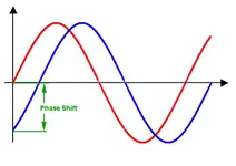
And in that light, let me back myself up a minute and clarify; I was just as off as Wikiworld, but in a different way. They are indeed correct in their chart to indicate the phase shift as being along the x axis (x + amount of phase shift). I correct myself there.

However the point I intended to make remains true; that chart does NOT indicate a time shift. the x axis in that chart is not a timeline, it is simply a number line of math values for plugging into a mathematical equation to determine y value. The red line simply shows the y values for sin(x), and the blue line the y values for cos(x). Yes, phase shift is indicated, but that is only in mathematical value, not in any kind of time shift. This is why both lines start at x=0 (the left side of the chart).

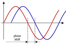
Now, if you want to look at a time shift, as in a DAW timeline, then you have something like the second diagram I put up, which assumes that x is not a mathematical value, but rather just an elapsed timeline. Note the important difference here, the second line no longer starts at x=0, it's simply been pushed down a bit. Yes, this very closely resembles a phase shift, but it's not; it's simply a time delay. The captioned gap should be labeled "time shift", not "phase shift", because in fact the phase of the wave has not changed at all, it's just that it starts later than the first.

This is an important difference because it indicates a) that phase shift is calculated independent of any variable of time, and b) that phase shift indicates a change in y value coming out of the phase equation, not a change in x value going into it (this is what I was trying to indicate with the green caption on my first revision.)

Much like (but not exactly like) a phase change of 180° (a so-called "phase inversion") closely resembles a polarity inversion, but only as a special case (only at 180°, and only with no DC offset), a time shift resembles a phase shift, but only partially (only at x values where both waves exist), and only with symmetrical, frequency-bound waveforms (like sinusoidal waves).

Yes, if you time shift a copy of a time line and sum it back with the original, they will not be phase coherent. But that's not because you have changed the phase of the original wave, only because you have delayed the start of it. Change the phase of the wave is something that happens "in place", with no time shift involved.

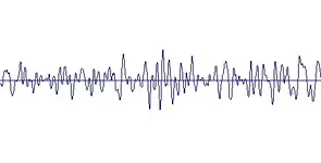
For proof in example. Attached is a real-life waveform as taken from a Sound Forge timeline. Here's two problems for anyone to solve and be king of this forum. By simply shifting this waveform in time, a) change it's phase by 180°, and seperately, b) perform a phase inversion that resembles a polarity inversion.

Anybody that can do either one of those by time shifting is a cross somewhere between Albert Einstein and David Copperfield. :D

G.
 

Attachments

  • sample_wav.jpg
    sample_wav.jpg
    32.3 KB · Views: 138
Last edited:
Attached is a real-life waveform .
Excuse my off the cuff ignorance here but isn't this an over simplification. Does any wave stand alone in real-life?
By simply shifting this waveform in time, a) change it's phase by 180°, and seperately, b) perform a phase inversion that resembles a polarity inversion.G.
Again isn't a phase shift only relevant to other waves involved in real-life?

One other thing I'm confused about is the x axis not representing time. I thought it represented the frequency which is time related. Can you help me out with that? I'm sorry I have a headache :)
 
Anybody that can do either one of those by time shifting is a cross somewhere between Albert Einstein and David Copperfield.

you are missing a fundamental point... complex waves can be broken down into a series of sine waves... therefore, with an infinite (sufficient) number of filters, one could break your example complex wave into the necessary series of sine wave components (magnitude and frequency) and then one can alter the magnitude (real part) or time shift (imaginary part) on each term.
 
you are missing a fundamental point... complex waves can be broken down into a series of sine waves... therefore, with an infinite (sufficient) number of filters, one could break your example complex wave into the necessary series of sine wave components (magnitude and frequency) and then one can alter the magnitude (real part) or time shift (imaginary part) on each term.
Agreed, and that's what functions like the Fourier transform and other related transform and filter functions are applied to.

But it still remains that once such filtering functions are applied, phase change can then be applied to the components with still no need to introduce time into the function. It is completely possible to phase shift a complex wave by a specific desired degree using these functions, and when doing so it is done in a time-independent fashion.

It is not possible, however, to do so via a simple time shift on either the compound wave or on the constituent components. If one wanted to break a complex wave down into simple sines, the amount of time shift would have to be different for each constituent frequency it has been broken down into.

G.
 
Having a EE degree I have good handle on time based functions and relationships, but frankly I haven't a clue what point you are trying to make over and over.

it sounds like you are trying to say that the Real part of i+jomega is sufficient to cause a phase shift.
 
Last edited:
Excuse my off the cuff ignorance here but isn't this an over simplification. Does any wave stand alone in real-life?
Again isn't a phase shift only relevant to other waves involved in real-life?
I'm not sure what you mean there, Star. It sounds kinda like" "if a waveform falls in the woods...." :D, , but I imagine that's not what you mean.

OK, "real life" is probably too trite a phrase to use there. All I meant was that it was a snapshot of an actual waveform from an actual sound clip that is used in a real-world situation (in this case it's part of the left channel of a stereo music mix.)

I was just trying to contrast against a simple sine wave as always shown in the textbooks. This is an important contrast, because when one looks at a complex waveform, the superficial resemblance that there seems to be between time shift and phase change that one sees when looking at sine waves, suddenly disappears when one looks at a complex wave the same way.

What I was asking was for soemone to demonstrate how that could change the phase of that wave (that original wave being the one to compare the shifted one to) by simply moving it up or down the timeline.
One other thing I'm confused about is the x axis not representing time. I thought it represented the frequency which is time related. Can you help me out with that? I'm sorry I have a headache :)
I know, this is a difficult subject to talk about, especially in this kind of medium.

Let's start with the given that "phase" as we're talking about here is a concept that transcends audio. Just like polarity, which is just as important of a concept when talking about car batteries as it is when talking about audio, phase appears all over the place (just ask your local bonded electrician or physics student :)), and not just in discussions of sound waves.

That chart that Wikipedia shows does not necessarily have anything to do with audio, and the chart is not a representation of a DAW timeline. It is simply a mathematical X/Y chart of the type we all had to deal with in high school algebra. It simply is a map of a mathematical function where x is the math value of the input into the function and y is the value of the "answer" that comes out the other end of that math function. Specifically, the red line is simply a map of the math function y=sin(x) , with a red point plotted for every y value result for every possible x value on the chart. Or in more layman's terms, it is simply a representation of a sine wave that s the sine of value x. The same is true for the blue line, which is actually a plot of the function y=cos(x), or the cosine of value x.

The mistake that is often made is that because an audio timeline on your typical DAW uses an X/Y chart to display things also, that they are showing the same thing. In fact they are not, the timeline in your DAW is using the x axis (horizontal) specifically to represent elapsed time, and the y(vertical) axis to represent the signal amplitude.

They're both X/Y charts but they're not charting the same kind of activity. The Wikipedia chart does not deal in time at all, no more than it deals with taste. That horizontal "shift" in the Wikipedia chart is not analogous to a horizontal or time shift in a DAW any more than it is representative of a change in the taste of the Excedrin you're probably taking right about now ;)

G.
 
Last edited:
Having a EE degree I have good handle on time based functions and relationships, but frankly I haven't a clue what point you are trying to make over and over.
Perhaps you can tell me which part of, "it doesn't require a shift in time to calculate a phase change" that you are having trouble with.

For example, where exactly is the time variable in cos(x) = sin(x + pi/2)?

I'll tell you what, sonixx, show me an explanation of the proper mathematical method for calcualting the new value of y by performing a phase change of p (rads or degs), explaining where a time change needs to be introduced, or where a simple time delay will affect said change p to the whole waveform, and we'll talk.

G.
 
Last edited:
Perhaps you can tell me which part of, "it doesn't require a shift in time to calculate a phase change" that you are having trouble with.

For example, where exactly is the time variable in cos(x) = sin(x + pi/2)?

I'll tell you what, sonixx, show me an explanation of the proper mathematical method for calcualting the new value of y by performing a phase change of p (rads or degs), explaining where a time change needs to be introduced, or where a simple time delay will affect said change p to the whole waveform, and we'll talk.

G.

the proper way to write this is sin(wt)

where
w = radian/sec
t = sec

seems to me that your analysis by just stating sin(x) is insufficient. time is the variable that determines the relative phase between two signals for a given frequency w, not gain.

an example of an ideal situation

Two mics

mic 1 (M1), t1 secs from source S0
mic 2 (M2), t2 secs from source S0

subjected to a sine wave with frequency

w (radians/sec)

and are separated by T seconds where T = t2 - t1 seconds

m1 sees the sine wave at t1 seconds
m2 sees the sine wave at t2 seconds

assume at time t0 = -t1 the sine wave leaves the source

The Gain coefficient allowing for air damping respectively is

A1
A2

therefore at any arbitrary time the mics see:

S1 = A1 * sin(w * (t0+t1))
S2 = A2 * sin(w * (t0+t2))

substituting

S2 = A2 * sin(w * (t0 + t1 + T))
S2 = A2 * sin(w * (t0 + t1 + t2 - t1))
S2 = A2 * sin(w * (t0+t2))

Now one can conclude that Gain coefficients influence magnitude and not the time based relationship (phase).
 
seems to me that your analysis by just stating sin(x) is insufficient. time is the variable that determines the relative phase between two signals for a given frequency w, not gain.
Your equations simply are a mathematical representation (with some extra glitz throw in in for physical material limitations) of the idea that a time shift on a sine wave yields results that resemble a coherent phase shift. This was agreed to by me and everyone else long ago. But that is exactly the point I am making that everybody is getting wrong. Time is NOT required to effect or define a change in phase angle.

Direct proof #1 of this is right in that Wikipedia chart. It's staring us right in the face The difference in phase angle between the two waves is exactly pi/2 rad - a.k.a. 90°. Yet there is no shift or difference in time. In fact, time doesn't even exist on that chart, because time is not part of the phase angle change equation. The phase change can be both defined and executed through simple algebra that contains no notion of time whatsoever.

For actual physical data supporting it, let's look at the existence of this thread at all. The very fact that people have a hard time telling the difference between flipping polarity and phase inversion is because with no DC offset present they look identical. And this is not with textbook sine waves, but with real world data. There is no time involved in calculating or executing a switch of polarity; it's simply a changing of signs. It's the same thing with phase inversion. Phase inversion of a complex wave does not involves any sliding of the wave down any timelines, it simply results in a mirror imaging *in place* of the waveform around the horizontal rest voltage.

Put simply, take that complex wave graph above, and flip it over vertically. No time changes at all. Show the two waves to a third party and ask them if the second were the result of a polarity change or a 180° phase change, and they, if they were honest, would say that there was no way from just those graphs to tell.

If one required a time factor to execute a phase change, then there would be a horizontal time offset between the two waves when a phase change were executed, and one could see the difference between that and a polarity flip, and the confusion, along with this thread, would be gone.

G.
 
Back
Top