Deacy build thread.

Hey all.
The little amp is going well, but there is one problem.
Ultimately the amp and treble booster work. They do what they should do. All pots and switches do what they're meant to do.


But....with the Treble Booster on and just a guitar lead plugged in, there's a permanent lower frequency feedback/buzz. Touching the jack tip kills it.


I figure this is some kind of ground issue, but I can't figure out how/why.

Sound familiar to anyone?


EDIT:
1054.png

Here's how I'm getting my +/- 9v.

If i touch either side of the left hand capacitor, all squeals/buzzes are fixed.
 
Last edited:
3 clips in the meantime for your listening pleasure.

2 with sm56 45degree, pointed cone centre.


and one with sm56 pointed straight at cone edge.
 
That is sounding as sweet as honey! Wow. Just wow!

Did you sort the hum issue? Which device are you using for the -9V conversion? Seems like some kind of grounding issue?
 
Cheers Paul.
The chip is LT1054.

Yeah, I added another cap across the power inverter chip as per some diagram I found.
I was hesitant because most simple diagrams I saw don't have it.
Seems to have fixed the issue though.


The cap goes between 9v and the + of the leftmost cap mentioned above. (pins 8+2)
I would appreciate it if you'd cast your eye. :)


My only concern is that a fully charged pp9 9v battery lasts about 3 minutes. :eek:

EDIT:
I put the meter in series with the batter supply and measured current in various states. (no guitar).

Cap in place
Amp = 118ma
Amp and booster = 128ma

Cap removed
Amp = 30
Amp and booster = 70.

Instructions state 12-14ma normal draw for the deacy amp, and I guess a further 10 is fair for the booster.

If I even touch my finger to LT1054 pin 2 or 4, the noises disappear but the current draw shoots up.


EDIT2:
Better yet, with the 9v and -9v chip outputs lifted (ie, no power to anything but the chip), I read 118ma!!!!
 
Last edited:
I had a quick look at the datasheet for the LT device.

Assuming you are using the basic voltage inverter from p. 10.

May not help, but...

1) Try floating pin 1.

2) Place a 2uf electrolytic across +V (pin 8) and ground

These are the differences I see between your posted layout and the datasheet circuit.
 
Hi Paul,
Thanks. It is indeed setup as per page 10.
Pin one was already floating. I should have mentioned that.
Adding 2uf cap didn't help.

Did you see edit:2 above?

There's large current draw with the treble booster and deacy completely removed.

I did the same test again but this time breaking the earth to the rest of the circuit.
Current draw fell to 3ma.

Presumably I have something leaking to ground somewhere, huh?
 
Last edited:
Paul, what's the best way to ground everything? Would you have each gnd point returning to the DC jack in a star?

I've proved everything to work fine on it's own, so GND is what I'm looking at.

I kinda had a 'strung along' ground system. I routed a few of them straight back to the DC jack instead and immediately improved the situation.
It's not completely sorted, but I think I'm on the right path.
The usage is now 23ma and 45 with the TB engaged.


I read this earlier in a star grounding description.
"The copper wires carrying "used" current back from the signal circuits also carries a tiny replica of that current in the form of a voltage across its small, but present resistance. This is shared resistance feedback; it does not cause hum, but it can cause your amp to be unstable and oscillate madly."
 
Last edited:
That high current figure was a concern for sure.

I'd definitely go for a star ground, and the DC jack is probably a good choice for star point. You could take the individual ground leads to a bit of tag strip, and then take a single lead to the jack. Maybe use a heavier gauge wire for the ground leads. I think you will get things sorted by experimenting with grounding.

I'd leave in the 2uf cap at the input to the LT1054, by the way. It might act as a reservoir during higher transient current demand?
 
Thanks for the advice Paul.
I star grounded everything today with limited success.
I discovered that my speaker negative wasn't grounded (as per deacy instructions).
Grounding it cleared up any issues when using the deacy amp alone. :):)


I still have a constant buzz changing to a squeal if I touch the jack tip when the treble booster is engaged.

I really don't know where to go from here, but I've emailed Nigel at the store to see if he can help.


Putting the 2uf in actually accentuates the noise, but it's meant to be there as you say, so I'll leave it there.
 
Last edited:
Bit of an update.

Nigel advised me to rewire the treble booster as positive ground and just do away with the inverter.
He was kind enough to draw up the changes for me so I have gone ahead and carried out his suggestion.

Now the booster and amp run on the same supply straight from one batter.
The problem is still there!!!!


If I break the signal line between TB + AMP I can feed the TB to an external amp and it's fine.
I can also tack a guitar cable on to the deacy and it's fine!!

Banging my head on the table a bit here...:p
 
Thanks to Steeno
I made my first working circuit from scratch. The treble booster.
The Steeno as its now called is now installed inside the Deacy. With In/Out Jacks so it can be used with external amps to or i can take it out of the chain.
I'm seriously impressed with myself. (polishes finger nails on his puffed out chest)
Thanks for the encouragement and help.
 
Nigel advised me to rewire the treble booster as positive ground and just do away with the inverter.
He was kind enough to draw up the changes for me so I have gone ahead and carried out his suggestion.

Now the booster and amp run on the same supply straight from one batter.
The problem is still there!!!!

Guess that simplifies the powering, at any rate.

If I break the signal line between TB + AMP I can feed the TB to an external amp and it's fine.
I can also tack a guitar cable on to the deacy and it's fine!!

Banging my head on the table a bit here...:p

How are you connecting the various sections - with a signal lead and return or just signal? Can you somehow do a diagram of the wiring?
 
Thanks to Steeno
I made my first working circuit from scratch. The treble booster.
The Steeno as its now called is now installed inside the Deacy. With In/Out Jacks so it can be used with external amps to or i can take it out of the chain.
I'm seriously impressed with myself. (polishes finger nails on his puffed out chest)
Thanks for the encouragement and help.

Have you experimented more with tones? Any more clips?
 
Hey kip. Glad to hear of your success!

Are you powering both the TB and the deacy from one battery?


Paul, That was my next step. I'm going to rebuilt the treble booster (for good measure) and draw a perfect diagram of what's happening right now.

Switching the treble booster in and out just breaks the gtr signal in and signal out and bridges them together. The grounds are all starred to the DC jack now.
 
i'm powering the deacy from a battery or dc walwart ( i managed to find a quite one) and the treble booster is also running off a pp3 9v battery.
No common dc supply. I figured it would be simpler to just power them by battery most of the time. I think i'll buy one of those guitar battery compartments for the treble booster battery and screw it on the back of the deacy to make it a bit more discreet and put an on off switch on the back panel for the TB battery too.
No Paul I havent had time to do much more playing with tones at the moment.
Works been flat out and in my spare time i've been trying to get my dumb ass brain round schematics and builds.
I should have done this years ago its something i've wanted to do since i was a kid and i watched my dad make radios.
Oh well i guess its not too late,
 
i'm powering the deacy from a battery or dc walwart ( i managed to find a quite one) and the treble booster is also running off a pp3 9v battery.

Man, I'm gona be pissed if I end up having to do that.


I'm gona completely strip everything apart tomorrow and run it on the bench. Then we'll really see what's happening.
 
Man, I'm gona be pissed if I end up having to do that.

I'm gona completely strip everything apart tomorrow and run it on the bench. Then we'll really see what's happening.

I'm guessing that somewhere there is a ground connection that shouldn't be, or a missing ground connection that should be.
 
Hey guys.
I did my tear down and bench test today.

I don't have an answer, but I've certainly simplified the problem.


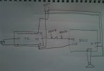
Screen Shot 2019-04-04 at 18.25.40.jpg


Wired as above, it's squeals like a mofo.


IF.....If pull DEACY + and - off the battery and stick them on another battery, it's all fine.
What does that tell us?
 
Last edited:
Did you say you had converted the TB to run from -9V? I'm a bit confused with the diagram.

All I can think of at the moment, before I turn in for the night, is to disconnect the shield between TB and deacy.
 
It's converted to be the same as the deacy. Positive ground.

There's 1 mistake in the diagram. Speaker - goes to positive...not negative as shown.
 
Back
Top