Tascam 246 wiggly input jack repair?

The Groke

New member
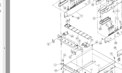
Hi. Does anyone here know how to best tighten the input jacks on a Tascam 246. It seems that they are held in by a little bracket. A couple of mine are very loose. Is it just a matter of bending the brackets for more tension?

Also, has anyone here replaced these jacks with screw-on chassis mount jacks for greater stability? Seems like it could be an easy change, but maybe the plastic would crack more easily from the stress. Maybe a metal plate in back across all inputs for added support? Seems like there is room. Would love to here some opinions on this.

Thanks!
 

Attachments

  • tascam 246 input plate jack.jpg
    tascam 246 input plate jack.jpg
    515.6 KB · Views: 12
Hi - the jacks are not mounted on a circuit board. They hang from that front plate and are secured via part #8 in that diagram above. So, there is nothing to re-solder (from what I can see). Or am I missing something?
 
Hi - the jacks are not mounted on a circuit board. They hang from that front plate and are secured via part #8 in that diagram above. So, there is nothing to re-solder (from what I can see). Or am I missing something?

So you just undo the clip and the Connector? I would say then that there should be a clip on both sides - if not get the clips. Or barring that put a little dab of super glue on them.
 
Hi. In the picture attached to my first post, there is only one clip, and that's about all I can see down into mine without taking out all the circuit boards. Sort of wondering if anyone has fiddled with these in the past so I can know if it's really worth dismantling. Maybe it's loose because some of the plastic threading around the input has cracked or worn off and that's what the metal nut thing (part #8) grips onto? Perhaps someone who has been inside these things could chime in?
 
The problem with these jacks is usually the broken solder joints due to too little solder applied. They made these cheaply not to high end standards. You can try and put a threaded in connector but you need to consider all the dimensions they need to fit into. The #8 clip part is a cheap replacement for a threaded nut. People might think these are better off with a nut but these threads are plastic so you can not torque down on them anyway- look around and see if you can find a metal bushing connector and then see if that will install but it seems like a lot of trouble for a deck that will need other work more importantly. Yes I have had to deal with those jacks a lot- the 1/4" connect gets pushed and put a lot of force on the connector as the plastic in these get old they will crack. In other words, the more these age the kinder you should treat them.
 
Hi. On this particular model, it's not necessarily an issue with solder joints. It's not like a behringer board where all the jacks are soldered to a giant circuit board and wiggling them eventually loosens those connections. Instead, each input jack has it's own circuit board. The jack and board then are both mounted to a metal plate via a U shaped clip. The clip grabs the plastic threading on the female input and each individual jack/circuit board assembly is held to the plate this way. Thus ZERO stress is placed on the solder joints.

I've come to realize that the reason mine wiggle is because the plastic threads that the U shaped clip are supposed to grab have worn off. So the clip now grabs a larger space the width of two rows of threading. Thus it moves around, but it has no impact on the actual soldering connections.

I think the easy solution is just to buy a new enclosed jack with a fresh set of threads. I guess metal would be a good option, but maybe there was a reason to isolate the ground of the sleeve from the chassis... so, being lazy, I'll just stick with plastic.
 
Look at parts 8, 9, and 20 on the pic I attached to my first post and you'll undertstand what I'm talking about.
 
I have had them open and worked on them so I know what is in there. The soldering of these parts is preposterous so even though there is no stress to it as if it was solidly mounted there is still stress from the plugs being torqued side to side and having the connectors sticking out the front will make that even more a common failure. Where wave solder is resolder it if you want reliability. Plastic jacks are also becoming more fragile in the use of plastic which harden a crack easier than they used to. Heat also add to the issue as in the case of VU meter lamps on a plastic Bayonet mounted lamp. These kinds of products were never anticipated to be working more than 7 years past when they were made.
 
If you can find a part that is metal bushing and with a nut then you might also have to cut a piece of aluminum to mount it and that would be stronger. They may be out there one would have to do research on that.
 
Hi Skywave. Thanks for the info. The free standing jacks are all secured to the same metal plate. Then the shaft of the jack sticks out through the plastic enclosure. Seems like there is plenty of room in there to mount metal jacks with nuts (instead of the clips) onto that plate. Would be much more secure (would obviously also touch up any soldering issues - mine seems generally OK though). Do you know if the plastic shaft was used on purpose for some grounding reason? Thanks!
 
No, it was used for cost reasons- anywhere they could shave off a dime they did it. If you can get jack with metal cushing and a nut then put them in and they would probably work a longer time. There are no grounding considerations if they are mounting that way- The ground is in the jack.
 
Back
Top