Still on track...

  • Thread starter Thread starter Michael Jones
  • Start date Start date
Michael Jones

Michael Jones

New member
... to submitt on Dec. 1, 2002.

So I thought I'd throw up a couple of electrical system lay-outs.
My thoughts are to have the elec. distributed as follows:

Control Room Lights - 1 20amp circuit
Control Room Outlets - 1 20amp circuit

Drum & Vocal Lights and outlets - 1 20amp circuit

Tracking Room Lights - 1 20amp circuit
Tracking Room Outlets - 1 20amp circuit

Kitchen, Bath, Storage - 1 20amp circuit

Mech (HVAC) - 1 50amp circuit

As always, thoughts are appreciated.
 

Attachments

  • elec2.webp
    elec2.webp
    31.8 KB · Views: 241
and here's the control room, et. al.
 

Attachments

  • elec1.webp
    elec1.webp
    49.2 KB · Views: 233
An "over-all"
 

Attachments

  • overall.webp
    overall.webp
    39.2 KB · Views: 509
Hey Michael - lookin' good, wish I was that far along.

The only thing I can think of you've probably already considered - making sure all outlets are on the same power phase, with lights/frig, etc, on the other phase. HVAC, of course, assuming it's 240 VAC, would have to be on both phases. I'd put heavy surge suppressors on both phases, probably at the blower motor hookup.

Even with the frig on the opposite phase, I'd get a super-duty surge suppressor to plug the frig into - If you can stop the switching spikes right at the source, it should keep them from ever becoming a problem.

For lighting, I'd stay away from ANY dimmers, and use flourescents ONLY for work lights. I've not experimented with halogens vs. noise, so no comments there.

Nice layout, BTW - should be super cool when it's done. I especially like using the bathroom as a soundlock for the mechanical... Steve
 
Hello Michael, wow, I must have missed an installment. I see you have incorperated
a diffuser in the rear wall. What are you using for materials, and what type is it. Or should I say, what did you use for the sequence? Your room looks fantastic. Are you building a fixture type console or ponywall with counters? I must say, I'm impressed.
Looks great, keep us up to date, ok?
Thanks
fitz
 
Can't help myself, Michael, what are you using for your monitors? And if you don't mind, the slideing glass doors. I've never seen them spec'd for a studio. Is this a special type? How do you effectivly seal at the tracks and where the doors overlap? One of those details no one ever mentions.
fitz:)
 
Knightfly - thanks for the comments and info, but I'm confused on a couple of matters:

1.) You say to make sure the 'fridge is on the opposite phase. But electricty is distributed as either 3 phase or single phase. Unless you're a hospital, factory, or warehouse, you're not going to get 3 phase electricty. So on a single phase distribution, what do you mean by keeping it on the other phase?

2.) You also say to use flouresents for the lighting, but my experience is that type of lighting is extremely prone to noise induction due to the ballasts. I was planning on using low wattage incandescent?


Rick - Yeah, I've been busy getting these plans into shape, and contacting contractors for prices.

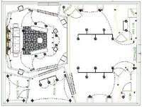
I had always intended to incorporate a diffuser on the rear wall, and it will be flanked by slot resonators as well. My intention at this point is to use birch hard wood for both. I'll set the diffusers onto a 1/2 birch plywood veneer and tilt it up as one "unit".

I must confess though, I got the idea from here:

CRBACK.jpg


The sliding glass doors and not necessarly studio spec. but they are double pane, exterior grade. With 2 of them, it should provide pretty good iso.
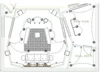
As far as setting the tracks, look at this pic:

Up6_9.jpg

See how the tracks are set flush with the floor.
the ones I intend to use don't pull together at the center though. One door is stationary, and the other one slides.
More importantly, at least to me, is how to seal the area between the 2 rooms, just past the doors with out creating a coupling? You can see what I mean on the far right hand side of that picture.

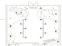
I'm going to build a pony wall with counters, and the outlets shown in the picture will be mounted below the counter, most likely as 4 double gang boxes.
I'm also going to incorporate channels into the slab for audio cables.

For monitors, I would love to be able to splurge on a set of ADAM's, but economics dictate that I use my Event 20/20 BAS monitors for now. John said he slipped a pair in at sjoko's studio, and that they sounded great. So, I'm going with those for now for the mains. I have a pair of Tannoy Reveal's for the near fields.

Special thanks to John Sayers for providing pictures to help illustrate my ideas!
 
Your plans are looking great Michael - Keep up the good work! It's funny, I am using both of the same pictures to describe to people what I am trying to do with my studio :)

On the area at the ends between doors, I am going to make a simple frame with 703 in it and attach it to one side only. It will be snug to the other but not really adheared... I'm not sure what else to do. I'd like to make them so that they are removable to gain access to the area behind.

Up here electricity is delivered as two phase. It is 240V across both or 120 across each... thats how you puwer stuff like electric dryers.

Couple of questions:

Why do you have switches on both sides of the control room?

Is there a window from the vocal booth into the control room?

Kevin.
 
Hmm, with regards to the electricty phase, I may be wrong (that's happened once before; one time when I thought I was wrong, turns out I was really right) but I believe electrical power for a residential building is single phase.

longsoughtfor - switches on both side of the control room? Seems like a good idea.
I may need to put a tracking room light switch in the control room too.

There is a window from the control room to the vocal booth, but I'm having difficulty detailing it because there's an audio monitor close to it. I can't move the monitor because it's geometry dependent. I think what's really gonna happen is the monitor is above the window. But, yeah, I still have to work on that.

Thanks for sharing your ideas.
 
Jonh - Fiber board?
Is that like masonite? You know, peg board without the holes?

And star earthing? Is all you're doing there is tying all your grounds to one common point?
Or is it such that outlet one doesn't have to pass through outlet 2 and outlet 3 to reach ground?
Can't you just tie the ground wire to the metal gang box for the outlet?

I'm confused?:confused:
You have a piece of romex (electrical wire) comming from your breaker box to the outlet. The black and white wires are hot and neutral, respectively. There's another wire, usually wraped in paper, and that's your ground.
So, star earth grounding is taking all of those grounds, bringing it outside of the gang box, and tieing them to an earth ground?

But you'e inside the wall, inside a building, above a concrete slab.
So either you have a penetration in the slab to ground, or you penetrate the exterior wall to tie to an earth ground?
Yes?, No? Maybe?
 
Last edited:
Just thought of something else.
Copper and concrete don't get along together very well. Concrete is very alkaline and tends to corrode copper rather quickly. Likewise, my soils are extremely akaline. I had a soil boring and geo-technical investigation done when I built the house to design the foundation.
 
Looking things over, I think I understand now.

So really, the only way to do this right is to have multiple copper rod penetrations through the slab.

Now, the trick is getting the copper rods set in the right place so that they end up in the middle of the stud wall.

Probably have to pull dimensions from 3 corners of the slab/form work to make sure they end up in the right place.

(Talking to myself here.....)
 
Back
Top