Oktava MK-219 transformer repair

  • Thread starter Thread starter evm1024
  • Start date Start date
evm1024

evm1024

New member
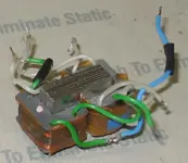
sweetbeats dropped an Oktaba MK-219 microphone by the other day. It was changing its output level bu 20 dB plus. At first we though it might be oscillating based on the output being changes when the transformer was touched.

After a bit of testing Beats and I decided that the transformer was most likely misbehaving.

In an email with Michael Joly I discovered that this is a typical failure mode for MK219 and one presumes MK319 (which have the same transformer etc).Correction: Michael says that it is a rare failure. My misquote.

He also sent me off to Oktava at: info@oktava-online.com where Natalia tells me that replacement transformers are 25 euro plus shipping.

Having nothing to lose I decided to repair the transformer....

--------------
Disclaimer: Hey if you do this you do it in full understanding that you are on your own and assume all responsibilities for the results. Heck, I did not do this to MY mic. I did it to Sweetbeats mic. What a great way to learn.
--------------

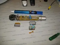
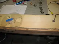
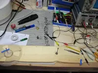
So the first thing is to get a clean, comfortable workspace and abouut 2 hours of un-interrupted time.

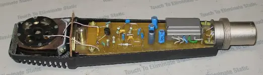
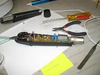
Then open up the mic and figure out where everything is. This photo is here to show me which wores go where.

Also, there are some very high impedences in a mic like this. THe board is coated with a conformal coating to keep moisture out. I often use pallbearers gloves (an nice white cotton glove) to keep my skin oils off the cap and 680 Mohm resistors.

--Ethan
 

Attachments

  • aIMG_5748.webp
    aIMG_5748.webp
    22.3 KB · Views: 205
Last edited:
Part 2: Open up that transformer

Once the mic is open up pull the PCB out and be very careful not to mess up the capsule.

The transformer is held on by 2 screw sets (nuts, washer, lock washer).

Un-solder the transformers wires carefully to preserve the PCB traces.

Once I had the transformer out I put the PCB back in the mic body to protect it.

Oh, I should tell you at this time to take lots of photos and to make a diagram of the wires so that you can reassemble the transformer later. Get a winding wired backwards and it really will not work.

With the transformer out you can remove the metal shell. The 2 halves just slide together.

Take a not of the tape position so that you can put it back as well.
 

Attachments

  • aIMG_5750.webp
    aIMG_5750.webp
    34 KB · Views: 206
Part 3: which winding is bad....

OK the transformer is out so we need to figure out which winding is bad. As you can see from the photo there are 2 bobbins on the core. We need to find out which one is the offender. Each bobbin has a inner output winding which goes to the XLR and an outer winding that goes to the mic electronics.

The output winding is of heaver gauge wire (if you can call this fine stuff heave gauge). These 2 windings are connected in series and all 3 wires are lead out (Left side , center tap, right side in you will). This winding is the inner one which is closer to the core.

The input winding is wound on top of the output and is of very fine and easy to break wire. I did not measure its gauge or turns (drats!). It is made up of 2 sets of windings with a layer of tape between them. (we will come back to that)

Now that we know how the windings are it is time to figure out which is bad.

I took an ohmmeter and measured each windings resistance all the while pressing on the windings to see if the value would change. The primary is about 35 ohms and the secondary less than 1 ohm. Whenpressing on one of the bobbins the primary on that winding weht to 50 or 60 ohms. Ha, gotcha.

wEll at this point it is time to remove some more tape and the cores. The core is a series of L shaped plates in a specific pattern. I used stainless steel tweezers (non-magnetic) to carefully remove the core piece by piece. All set down with a note to remind me how to put it back together.

Here is a photo of the disassembled core pieces and of the bad bobbin.

Notice the documentation.....
 

Attachments

  • aIMG_5752.webp
    aIMG_5752.webp
    33.8 KB · Views: 197
  • aIMG_5753.webp
    aIMG_5753.webp
    28.8 KB · Views: 196
Part 4: Unwinding

Having the offending winding identified and the core pieces out I was able to remove the bobbin and start on it. Off came a layer of tape and then some turns of thread (you can see the black thread in a photo in part3).

I needed to unwind the winding so I found some scrap wood and an ampex reel to make this jig. The first few turns were unwound manually and when I had enough wire off the bobbin I placed it as you see.

The bobbin on the right with a nail through it and the wire leads helping to let it turn smoothly without jerks.

The wire lead goes to the reel and is taped outside the spool.

Then I was able to turn the ampex reel very gently so as not to break the magnet wire. Sometimes the wire would hang up on the bobbin. When that happened I would gently pull the wire by hand to help it along. Very gently...

I kept stopping and measuring the resistance of the winding to see what would change. Looking for a point when the resistance would not change when the bobbin was pressed on.....

At last I came to the junction of the 2 halves of the primary winding. It appears that a first half is layed down then a layer of tape and then the second layer. THese 2 halves are joined with a soldered joint. BINGO! Problem found.

It turns out that this solder joint failed. Mechanical movement would make is better or worse. Out cam the solder Iron and some silver solder and they were rejoined.

Resistance measurements showed that this indeed was the problem and that resoldering it fixed it.

N.B. Soldering wire this fine is a problem. The wire is typical magnet wire of very fine gauge. It is about half the diameter of a fine hair and coated with enamel insulation. This presents a problem. You can scrape the insulation off with very fine sandpaper or burn it off with your iron. Sanding will ofter break the wire and does not get all the insulation off. Burning it off will if you are not very careful melt the copper magnet wire or dissolve it into the hot solder. I elected to melt it.
 

Attachments

  • aIMG_5754.webp
    aIMG_5754.webp
    31.4 KB · Views: 185
  • aIMG_5758.webp
    aIMG_5758.webp
    41.5 KB · Views: 180
Part 5: rewinding....

OK it was late at this point so there are less photos. I took an electric drill motor that had a variable speed trigger and a trigger limiter and made a jig out of a wooden pencil that I could fit the bobbin on. Testing the drill I set the maximum speed to about 2 turns per second.

I took the ampex reel and changed it so that it would feed with as little friction as I could get. The reel was not vertical rather than horizontal and resting on a piece of round plastic that formed an axle. Just think about turning the scrap wood 90 degrees.

The bobbin was fitted on the drill and everything aligned. Off we went at 1 turn per second. THis took quite some time as that there might be 500 to a 1000 turns. I used my finger to place where the wire went on the bobbin for an even laydown and to feel the tension.

At one point the wire caught on the ampex spool and broke so I get to solder that thin stuff again. (or was it twice again?) A little tape to cover the winding and off we went at 1 or 2 turns per second.

Long story sort. The wire was all back on and then the black thread goes back and then the tape.

N.B. Keep track of the direction that the wire comes off. You need to rewind it the opposite direction when going back on. If it turns clockwise coming off then you will need to turn counter clockwise to put it back and keep the phase. Won't work right otherwise.


Lastly, I took the 2 bobbins and clamped them together in a smaller wood clamp. This gave me a fixed "platform" to put the core pieces back in.

They fell out a few times until I took some tape (blue masking tape in fact) and held the first set of core pieced in place.

One by one they went in in reverse order of how they came out. They are very loose and prone to falling out or being pushed out till you have about 80% of them in. then they start to feel more solid and easy to work with.

It took me a few tries to get it right.

Anyway, here is a photo of the reassembled transformer. Not quite as compact as before but I was feeling quite happy about it.

THe leads were soldered back together according to the drawings I made and the heatshrink replaced.

One final check of the windings resistances showed me that indeed pressing on the bobbins did not change the resistance.

Yes, it is fixed but part of me says for how long? Just buy a transformer and be done with it.
 

Attachments

  • aIMG_5759.webp
    aIMG_5759.webp
    19.3 KB · Views: 177
Part 6: testing

OK, all this took 2 or 3 hours. Not exactly what I wold call cost effective but it was rewarding and interesting.

With the transformer reassembled and placed back in its metal shield it goes back into the Mic. When putting the transformer into the shield you need to pay attention to where the various lead wires go to be sure that it wires up correctly. The drawings I wade were quite helpful.

Once assembled I put it inthe PCB and screwed it down then resoldered the leads to the pcb as shown in this photo.

lastly the mic body was replaced and we were ready to test.

Testing was easy. I just got a DMP-3 that I had laying around and hooked it up to the mic and to a headphone amp.

It was clear from the beginning that the mic was operating better. It was much more sensitive and banging the mic around did not change this. Before the fix the mic would start out at low sensitivity and go more sensitive as you moved or banged on it.

I shook it around a bit and not once did it cut out.

Of course the mic body was ringing but hey this is a MK-219 and they ring. Fixing that is another story.

------------

So there you go. Happy DIY.

Regards, Ethan
 

Attachments

  • aIMG_5760.webp
    aIMG_5760.webp
    35.5 KB · Views: 172
:eek:


...:eek:


Whoa...

I had NO idea you were going to take it to that level...wow. I thought, um, you were going to test and say "buy a transformer and be done with it." I guess you did say that, but after you repaired the transformer...:eek:

Okay...well, I tell you what...your writeup of this repair (which is also impressive) tells me one thing: I won't ever repair a transformer. This has great value.

Ethan, a sincere thank you for taking the time to journey into the inner windings of this (figuratively and literally), and for taking the time to share the findings and process.
 
...
In an email with Michael Joly I discovered that this is a typical failure mode for MK219 and one presumes MK319 (which have the same transformer etc).

Actually I said this: "Hi Ethan, that is a rare fault mode of the 219 - but does occur sometime".

In fact, out of 700-plus 219 / 319 mics I've had exactly 2 transformer failures and have heard of a couple more. So folks should not get the idea this is a "typical failure mode". I don't mind if people quote me, because I parse my words really carefully - but if you're going to paraphrase, please apply as much rigor to language as to troubleshooting and get it right. Thanks ; )
 
.................

Ethan, my hat's off to ya, man! I wish I had your skills and patience. Well done, well done... :)
 
Oops!

Actually I said this: "Hi Ethan, that is a rare fault mode of the 219 - but does occur sometime".

In fact, out of 700-plus 219 / 319 mics I've had exactly 2 transformer failures and have heard of a couple more. So folks should not get the idea this is a "typical failure mode". I don't mind if people quote me, because I parse my words really carefully - but if you're going to paraphrase, please apply as much rigor to language as to troubleshooting and get it right. Thanks ; )


Michael is right I did mis-quote him. He did say (as above) that it was a rare fault mode. Pretty much the end of our conversation.

And I then speculated to myself that of the transformers failures I suspected that the solder joint I found would be a typical failure provided that soldering was either by design or to repair a break during construction. I ofcourse have no information on the design or construction practices and was purely speculating. And to add insult to injury left off all those disclaimers.

The fault lies with me.

Regards, to all.

--Ethan
 
Just to be pedantic, 2 out of 700 isn't what I'd call a rare failure mode (unless you mostly see broken mics, Michael). If that's even approaching a random sampling of the units out there, a .28% failure rate of any single component is pretty bad.

To put that in perspective, a .28% failure rate is about half the annual failure rate on the older line voltage oil transformers you might have outside your house (and three times the failure rate of some of the better, more modern transformers). By contrast, this is for a transformer running at low voltages indoors with no possibility of water getting inside it? That's nuts.

For modern audio transformers, I'd expect maybe... maybe 0.02% to come off the manufacturing line with an open winding, but those would be caught immediately. I'd expect the field failure rate beyond those to be undetectable.

In short, I think perhaps the QC on those solder joints is less than ideal. Admittedly, it's also possible that Michael has seen every single MK-219 whose transformer ever failed.... :D
 
...Admittedly, it's also possible that Michael has seen every single MK-219 whose transformer ever failed.... :D

I think that's closer to the truth - a much larger installed base of mics in other words. There are over 90,000 MK-219s in operation and transformer failure is just not on our radar as even a minor problem.
 
Back
Top