My fancy new pedalboard

  • Thread starter Thread starter thebigcheese
  • Start date Start date
thebigcheese

thebigcheese

"Hi, I'm in Delaware."
The February DIY challenge has motivated me to finally go out and get some real wood to build a real pedalboard. The first picture is a drawing I did to help me figure out what I was going to need and how it was going to work out. The second picture is of all the measuring and lines I had to make in order for my plan to work. I wanted to have a sort of grid pattern of holes in the board, similar to this commercially-available board:
543624.jpg
 

Attachments

  • IMG_0339.webp
    IMG_0339.webp
    25.2 KB · Views: 208
  • IMG_0341.webp
    IMG_0341.webp
    32.8 KB · Views: 213
And this is where I'm at now. My jigsaw decided to crap out on me on the last couple slots, so I'm hoping it will fix itself magically overnight so I can finish. The next step is to sand everything and figure out what I'm going to cover it with. Probably some sort of carpet material so I can just attach pedals with velcro. Before I put that on, though, I need some help. You'll notice that at the bottom, two of the slots don't go down quite as far. I want to put a bunch of bypass switches there, about 8 or 9 (the last one would be a master bypass), but I don't really know now to wire it all up. I have to make sure there's room so the cables don't get squashed between the board and the floor. I'm not sure if it makes more sense to have switches with 1/4" jacks on the bottom or if I should just run some cable out of each switch and make sure it's long enough to plug in anywhere on the board. Can someone help me out with this part? I need to know where to get the switches, how to mount them (should I get some sort of metal enclosure?), and how to wire them all up. Thanks.
 

Attachments

  • IMG_0343.webp
    IMG_0343.webp
    35.3 KB · Views: 210
Looks good!

I built a hacked-together board recently that i plan to redo and improve on a bit. A couple things i would recommend, and easy to reach power switch and a drawer or something similar to store things out of the way, but still within reach.

Good luck,
Daav
 
Well, the jigsaw didn't fix itself, but I figured out how to get my Dremil to cut that last hole, so now it's on to sanding! Ugh.
 
Ok, here it is after all the cutting and sanding is done. It doesn't really look all that different, I guess, but the edges are smoother. I'm trying to decide what the next step will be... should I get some carpet and glue that on first, or should I put on the rear support thing? And then I need to figure out where to get all the stuff for the bypass strip. I found a site that says how to put it all together, but I'm still a little confused.
http://www.premierguitar.com/Magazine/Issue/2007/Nov/The_DIY_True_Bypass_Lesson.aspx
Why do I need a stereo jack for the master input? Has someone else done this before that can help me out? I need to know where I can get a metal box for the strip that's about 22.5" long (8 switches and a master bypass). Does Radioshack sell the switches and things, too, or am I going to have to order everything?

EDIT: I have the confidence booster kit from BYOC. Will that work as a buffer for the bypass strip? It would save me a lot of trouble.
 

Attachments

  • IMG_0344.webp
    IMG_0344.webp
    26.2 KB · Views: 183
Last edited:
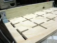
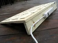
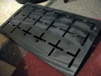
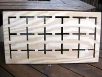
The board looks nice. Good work! :)

Now, as for how to wire thing this is kind of depends. To my mind the whole idea of making your own board is all about making it the way you like and so it makes your PERSONAL guitar playing life easier and more pleasant, sort of speak. I was myself about starting building a board, but never got actually into it as I still am not sure how exactly I want it to be. It has to be custom all around, and custom means NOT! universal :p. See what I mean.?

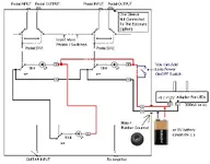
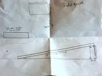
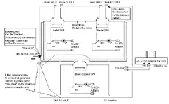
I've made up a diagram for you (attached), which shows you the basic idea about how I would approach the "system". This is only the basic idea. It's easier to draw a sketch that to type words about this stuff.

Couple points:
1. I would put the switching "system" into metal box, that's for sure.
2. Next you need to be careful about how to actually wire it.
3. I would add LEDs for bypass switches, showing you what's "IN" and what's "OUT". To add leds would mean to be using "tripple" two position switches.
Here's eBay links to someone who sells this stuff, I am not sure about prices, though, you may find them somewhere cheaper:
link: http://cgi.ebay.com/3PDT-SWITCHES-TRUE-BYPASS-NEW-EFFECTS-BOUTIQUE-ROHS_W0QQitemZ200308436663
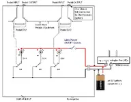
If you really don't care about LEDs, then you need this kind switches, link: http://cgi.ebay.com/DPDT-FOOTSWITCH-TRUE-BYBASS-EFFECTS-WAH-PEDALS-NEW_W0QQitemZ200308435069QQihZ010
, btw, that seller got all sorts of parts for guitar/pedals and such projects, prices looks ok to me, but not really "sockingly cheap" ..heh heh

You sure can either have IN/OUT jacks for the pedals, or have short cables with TR plugs comming from the box. I would build a custom box, I would go for short cables with plugs and no jacks (less purts overall and the same result).

I have no clue where to find the metal enclosure that is ready to go and fits your design. I would make something up from crap-scap pieces, that's the way I make 90% of my "gear" :D
Re-use something :)


Good luck with your projects. Keep posting.
Here's diagram. Ask a specific questinon, if any.
 

Attachments

  • dr_zee_pedal_board_bay_sketch.webp
    dr_zee_pedal_board_bay_sketch.webp
    22.7 KB · Views: 171
I have the confidence booster kit from BYOC. Will that work as a buffer for the bypass strip? It would save me a lot of trouble.

Build your board system first. Test it. If you REALLY start noticing "things" (like you "loosing your "tone" and such ,...heh heh) , then deal with it. Then you can try to add some buffer/driver. In a sense , it's a just a pedal (#1) in your chain, that's all. :)
 
Why do I need a stereo jack....
That's if you want to "add" automatic pedals' power ON/OFF. When the plug in not inserted, negative terminal of the pedal's power supply is disconnected (it is connected to the Ring terminal of the stereo jack). When you plug the TS (mono) plug into that "stereo-jack" the sleeve of the mono plug connects ground (sleeve) terminal and the ring's terminal ("-" of the power supply of the pedal (your bypass strip in this case) and the power turns on. It's good when the supply is a battery.
Now, I personally would not do this stuff this way at all.
I would power the LEDs completely separatley with a wall-type adaptor (9-12 VDC, 250 mA or so), and I would not even connect the negative of that LEDs power line with ground (enclosure) at all.
Also, I kind of don't get the whole idea about that bybass circuit. For "bypass" I would simply cut the pedal out of circuit of the system completely (think of symply unpluging it), period. So in bypass mode the pedal only has one single ground connection with the rest of the system, and nothing else. The input of the pedal that is bypassed is NOT grounded, but so what? It's out of picture. What am I missing here? :o
:D
 
Build your board system first. Test it. If you REALLY start noticing "things" (like you "loosing your "tone" and such ,...heh heh) , then deal with it. Then you can try to add some buffer/driver. In a sense , it's a just a pedal (#1) in your chain, that's all. :)
Thanks for the diagram (and the links)! I'm not sure I understand all of it, though... How does the power supply plug connect to all those LEDs?

I'm thinking I'll go with the jacks, but mostly because I'm not really sure how I would go about connecting a cable directly to the switches and then how I would keep it securely in place (which is a big concern with guitar rigs, obviously).
 
That's if you want to "add" automatic pedals' power ON/OFF. When the plug in not inserted, negative terminal of the pedal's power supply is disconnected (it is connected to the Ring terminal of the stereo jack). When you plug the TS (mono) plug into that "stereo-jack" the sleeve of the mono plug connects ground (sleeve) terminal and the ring's terminal ("-" of the power supply of the pedal (your bypass strip in this case) and the power turns on. It's good when the supply is a battery.
Now, I personally would not do this stuff this way at all.
I would power the LEDs completely separatley with a wall-type adaptor (9-12 VDC, 250 mA or so), and I would not even connect the negative of that LEDs power line with ground (enclosure) at all.
Also, I kind of don't get the whole idea about that bybass circuit. For "bypass" I would simply cut the pedal out of circuit of the system completely (think of symply unpluging it), period. So in bypass mode the pedal only has one single ground connection with the rest of the system, and nothing else. The input of the pedal that is bypassed is NOT grounded, but so what? It's out of picture. What am I missing here? :o
:D
Ah. Well, I'm going to have all the pedals plugged in anyway, so I can just use a mono jack then?

Why wouldn't you connect the LED negative to ground? Would it just not be connected to anything?

I can't answer your question about bypass :P But if it's supposed to help and it won't hurt, why not?
 
I'm thinking I'll go with the jacks, but mostly because I'm not really sure how I would go about connecting a cable directly to the switches and then how I would keep it securely in place..
That's a good reason, actually. It can be done, but a bit more of crafty-work. Saves you few bucks (minus sixteen jacks and sixteen plugs), that is if you are making your own short cables. If you already have bunch fo those pedal cables, then it's kind of easier to go jacks-way. Jacks are pretty cheap (a kind of them are, that is :)).


I can't answer your question about bypass..
It's ok. It was not a question ;)

Ah. Well, I'm going to have all the pedals plugged in anyway,....
but of course :)
The idea of having that stereo jack for "master" is similar to all pedals that you are plugging in into your "switch/bybass box". Chances are that all your pedals (or most of them) have that "feature".
The bypass box itself is a 'passive' system, no power. But the leds need power. So the idea 'there' is, that you have you leds powered by the battery, and you only have the battery power "ON" (so the LEDs suck the juice out of battery like no tomorrow) when you plug the "master" plug. When you unplug the master - you turn the leds "OFF" and the battery goes to sleep. :cool: But if don't unplug and keep some switches "ON"... you know. So have to keep unplugging ...heh heh
Again, I would power the leds by an adaptor. Unless you have unlimited free source of batteries and don't mind wasting time changing them.

Why wouldn't you connect the LED negative to ground?
?
To keep anything unrelated to Guitar effects "system" away from the Guitar effects "system"

Would it just not be connected to anything?
?
Nop. it would not.
Here. I've edited the diagram, to show the connection for the leds. Make sure to get LEds polarity right + to + / - to - , link: http://www.societyofrobots.com/images/electronics_led_diagram.png
 

Attachments

  • dr_zee_pedal_board_bay_sketch_leds.webp
    dr_zee_pedal_board_bay_sketch_leds.webp
    16.7 KB · Views: 158
Oh, so you connect the negative of the LEDs back to the negative of the power adapter? And otherwise, you're basically just chaining them all together, right?

So if I don't do the stereo jack thing, the only thing that won't work without power is the LEDs, right? Assuming all the pedals are still plugged in, I could operate the bypass strip without powering it? Well, if I put a buffer on there, that would probably need it, too, right... Do buffers go before the pedals or after them? I think I've read both ways, so I'm a little confused. Is one way better than the other?
 
So if I don't do the stereo jack thing, the only thing that won't work without power is the LEDs, right? Assuming all the pedals are still plugged in, I could operate the bypass strip without powering it??
That "bypass system" is nothing more than an electronically passive mechanically active switching device of convenience :D:D:D It does the same as you would plug/unplug connect/disconnect your pedals in and out of your pedals' chain between the guitar and the amp.
The power there is for LEDs only.
All your pedals are separately powered either by their own batteries or adaptors (or by a multi-power block)
...if I put a buffer on there, that would probably need it, too, right... Do buffers go before the pedals or after them? I think I've read both ways, so I'm a little confused. Is one way better than the other?
Think of that "buffer" as another pedal. And again, I'd say, think about it after you build the box and try with your effects etc. You may or may not feel (hear that is) that you need another "buffer-effect" ...heh heh. If you hear that it sounds like you loosing something with your pedal chain in full bypass mode, then you can either make a buffer-box (just like another pedal) or you can build it in inside the switching box. Reserve some space ther if you feel like it. And, sure, the buffer circuit will have to be powered (just like any other pedal, that is).
btw,
When you have a bunch of pedals in your chain you also "have" a bunch of all sorts of "buffers" there. They do good and they do some not so good. It all depends. It's a long topic really.
The whole idea of "true bypassing" is to completely take the effect box with all its guts (or boxes) out of the "picture". As I understand, The "theory" there also is that the bypass switching box with all the wires/switches/connectors can suck some "life" out of your "tone" and thus a some sort of "fancy" buffer should save it all. :D You gotta try, to get a taste of whether or not there's any truth to that by your own conclusion.


Oh, so you connect the negative of the LEDs back to the negative of the power adapter? And otherwise, you're basically just chaining them all together, right?
Not chaining per say, but rather hooking in parallel, here's edited diagram:
 

Attachments

  • dr_zee_pedal_board_bay_sketch_leds_2.webp
    dr_zee_pedal_board_bay_sketch_leds_2.webp
    15 KB · Views: 159
But I mean, you're still basically connecting the LEDs together, right? It's not some kind of fancy cable or anything.

I'm beginning to think that this whole bypass strip thing is going to cost way more than I thought it would. I mean, that's at least $30 just for the switches, then the addition of all the jacks has got to be another $30 minimum, all just to eliminate a little bit of pedal noise... It might be more efficient (cost efficient, anyway) to just make some single-switch boxes later if the noise really bugs me that much. Thanks for all the diagrams and pointers, though. I'll probably end up using them eventually, just not right now.
 
I'm losing sleep over this thing... can't sleep until it's finished! Here's where I'm at right now. Late last night, I decided to screw on the rear support/propper upper thingy. I still need to get a smaller brace for the middle, as the big one I have doesn't really work so well with all the holes I cut. Oops. I forgot to put glue between the boards before I screwed everything in, but I don't think it'll matter too much. I might put some in the cracks anyway, though.

This morning I decided that the outside was the best place for the power strip because the adapters don't fit if it's on the inside and I don't want it taking up space on top. I used screws to hook it on, then some nails to make sure it stays in place and to keep the cable on the board. I'm going to get some big zip ties to keep the adapters on the outlet strip, I think. I have a couple ideas for how to run the cables inside, but I'm not sure which one is best yet. I could either run them over the top and into the holes that are already there, or I could drill a hole in the back and run through there. I'm leaning toward drilling the hole, though. Now I just have to wait for my laundry to finish, then it's off to the store for some carpet! Ideally, since I'm not going to do the bypass strip just yet, I would like to put input and output jacks on the side, but then I have to figure the best way to do that. If I can just get a cable with a 1/4" female on one side and a 1/4" male on the other, that might be easiest, though I'd still have to figure out how to mount it...
 

Attachments

  • IMG_0346.webp
    IMG_0346.webp
    27.7 KB · Views: 153
  • IMG_0347.webp
    IMG_0347.webp
    28.8 KB · Views: 152
I'm sorry Big, but that's lookin' pretty "cheesy" now.

Whatever, party pooper. Like always, I was a little over-anxious in putting that power strip on, so I took it back off to paint. It's started too look better :) I now have to make some decisions. I got some carpet and I also got some grip liner stuff, like what they sell for you to put cell phones on in cars. On the one hand, the grip liner stuff will look nicer (I think), but on the other hand, it won't work very well if I put the board in a case and carry it sideways. Well, not as well as velcro on the carpet would, anyway...

I went to RadioShack and got some stuff for the input and output jacks. I got two mono jacks and two 3' cables that I can connect to them. I also got a little plastic enclosure that I can use to put around the inside so that I don't have to worry about the loose cables getting yanked. I'll probably just put some sort of glue around the holes that I run the cables through to prevent yanking.
 

Attachments

  • IMG_0348.webp
    IMG_0348.webp
    35.8 KB · Views: 142
Looking forward to seeing how this turns out.

I did something similar not too long ago instead of getting a Furman SPB-8C...I didn't actually build my own board though. I just got a nice big plain board from Rondo, then built my own patchbay and added a Furman power block. Already had a power supply for the pedals.
 
Back
Top