N
Neve1073lover
Inset French Saying Here
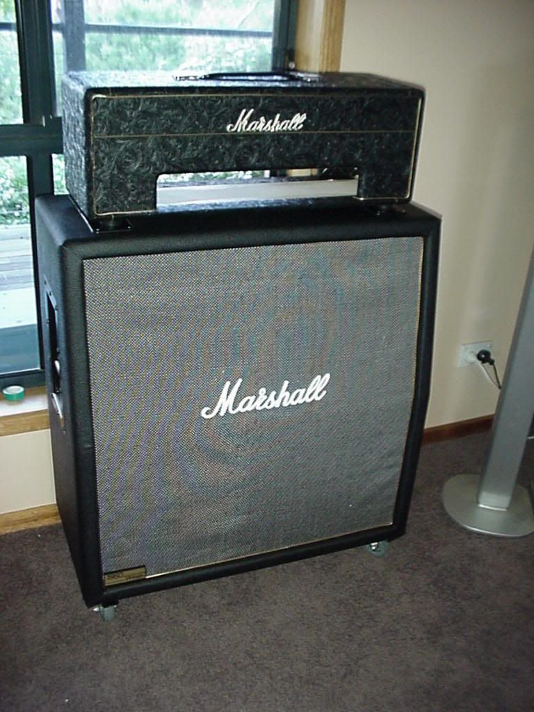
Got so carried away with my Neve thread, I thought I would show my Marshall 4x12 100W build:

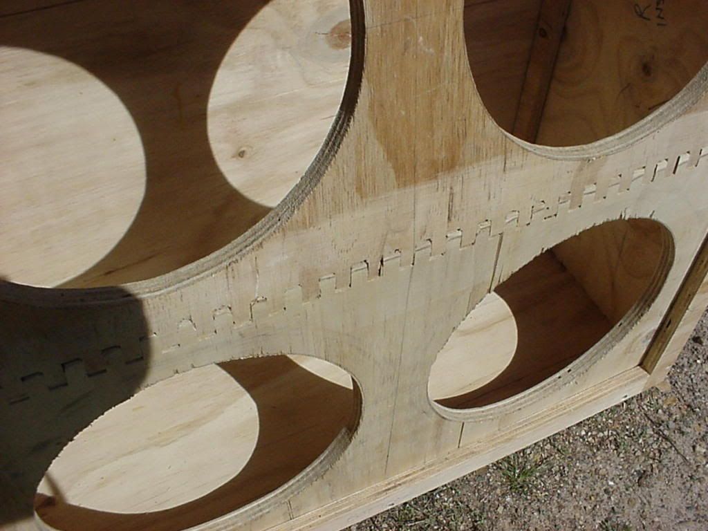
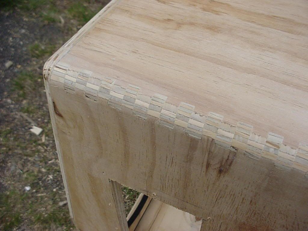
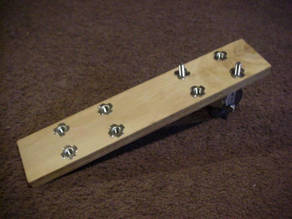
Fingerjointed the front panel. Never Again...
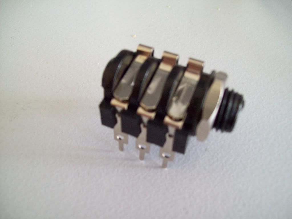
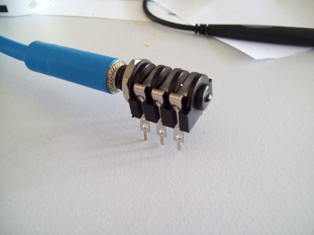
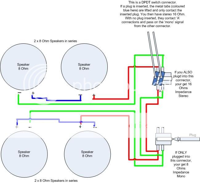
Greenbacks. Used 4 x 25W 8 ohm. 2 lots of 2 in series (16 ohm), then in parallel, making an input impedence of 8 ohm:
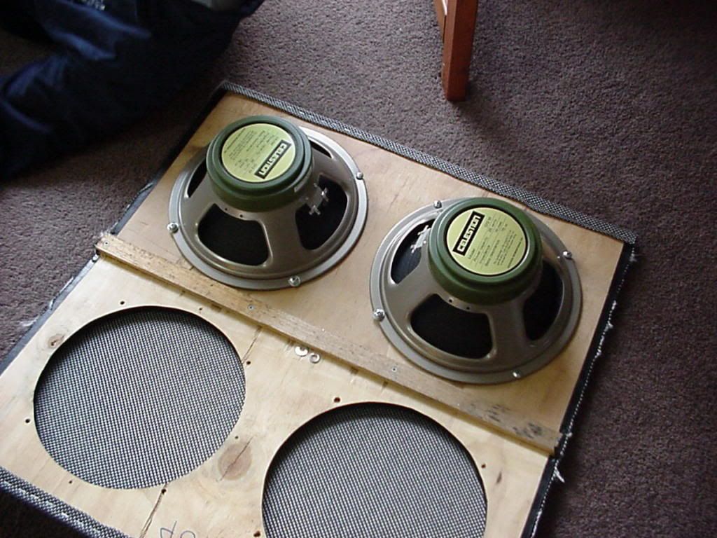
Left input is mono 8 ohm, use both and automatically changes to stereo 16 ohm.
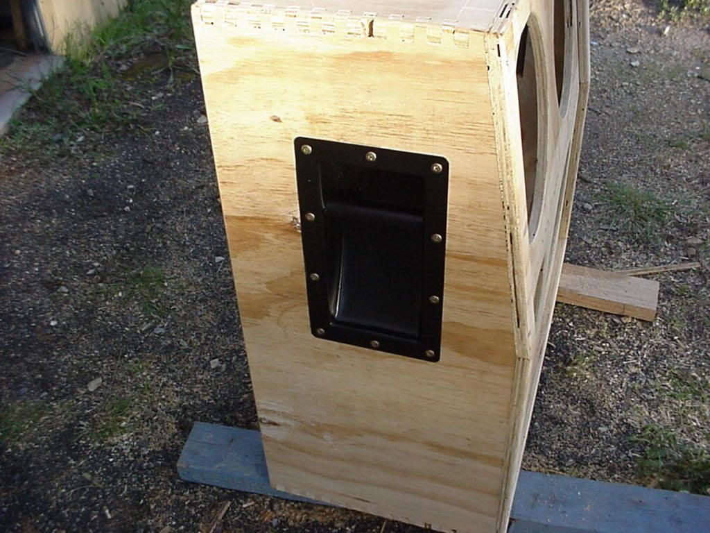
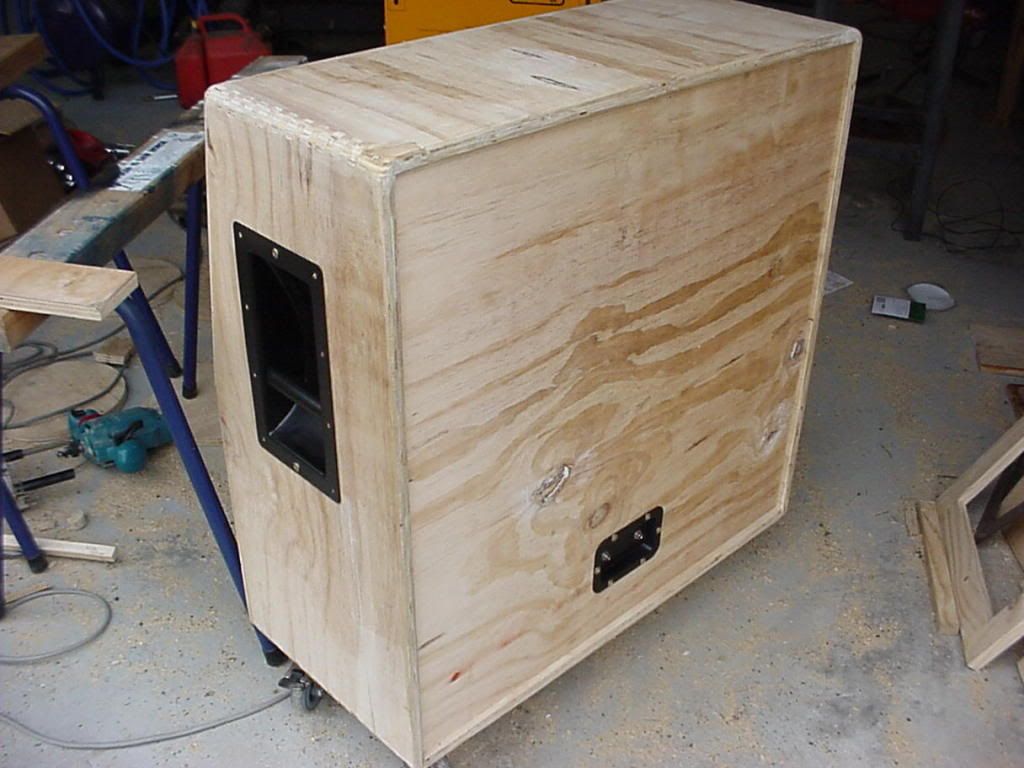
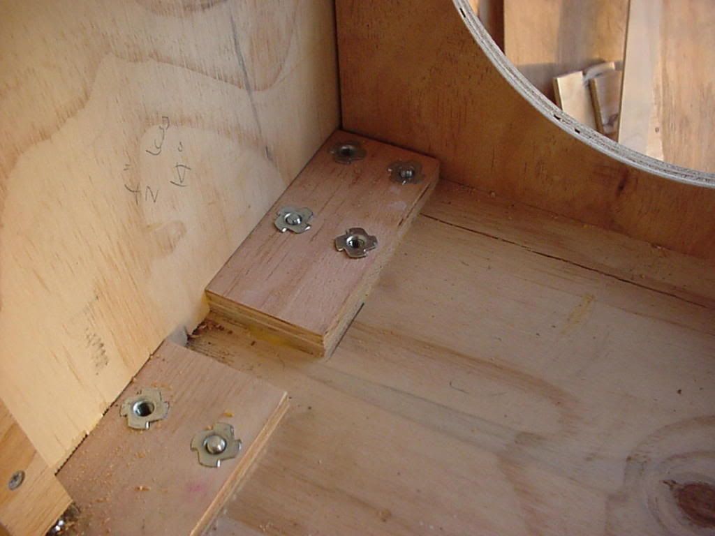
More fingerjoints:
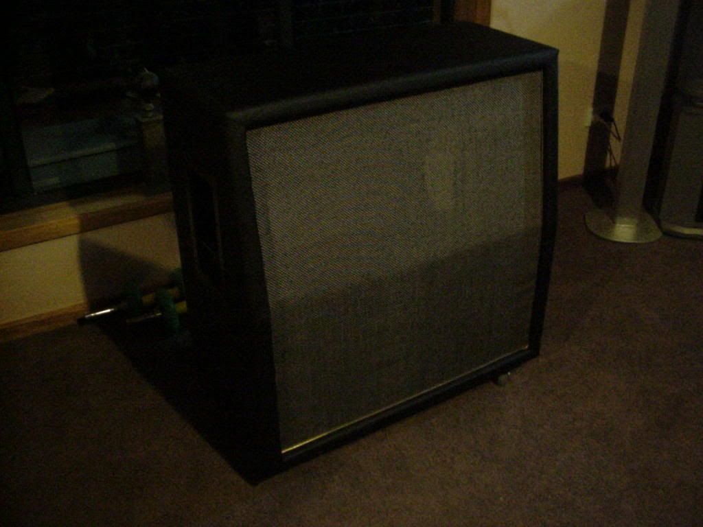
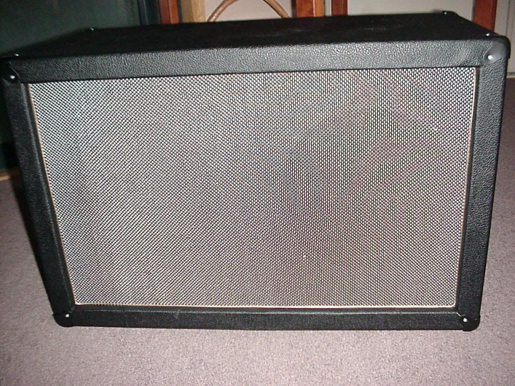
Salt and Pepper grillcloth:
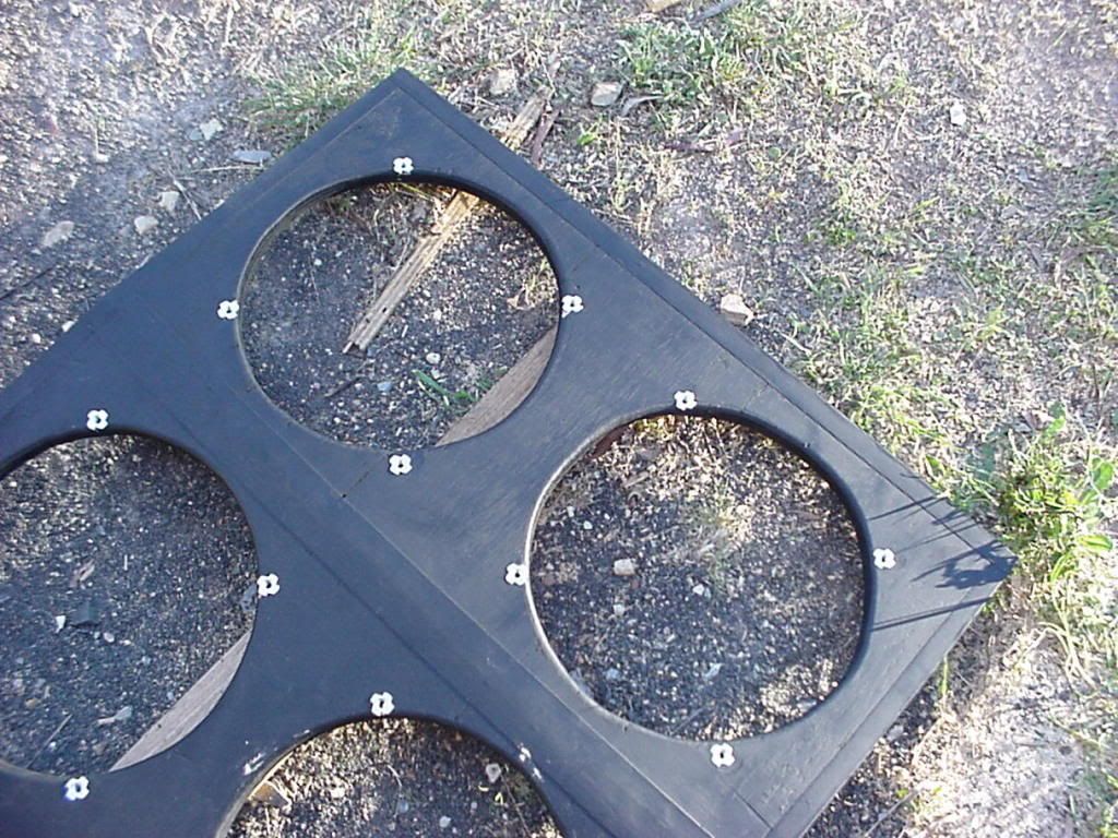
Proper Tolex design:
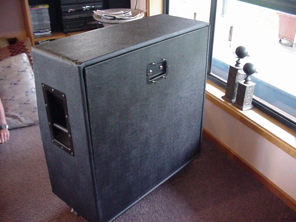
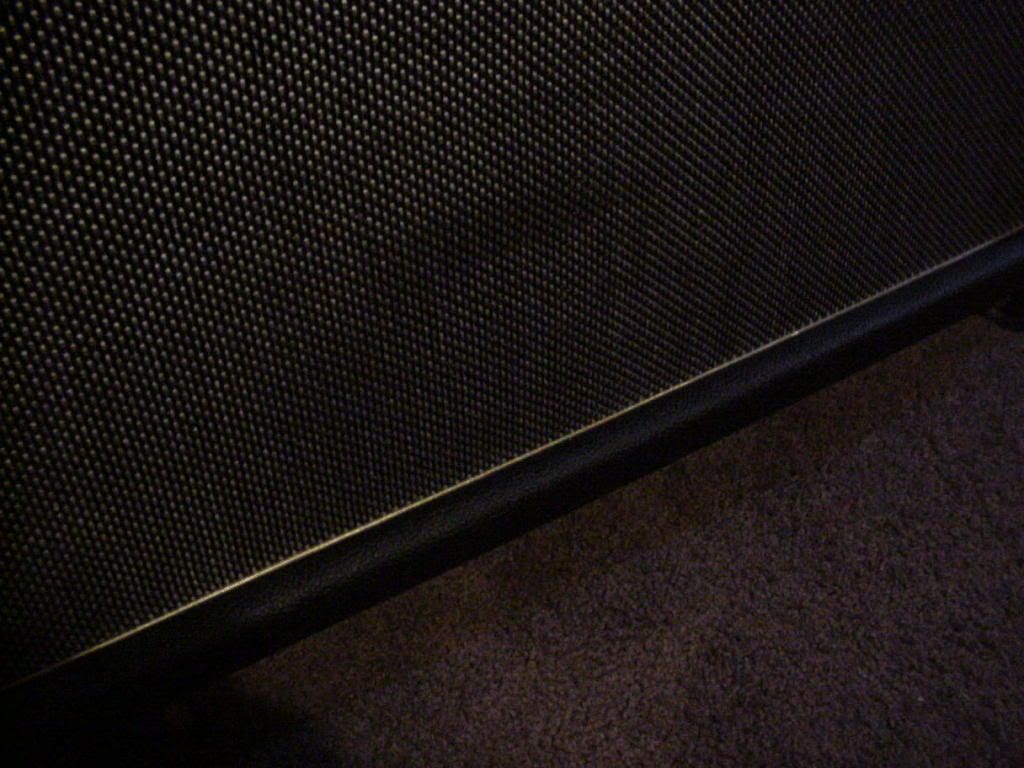
Gold piping:
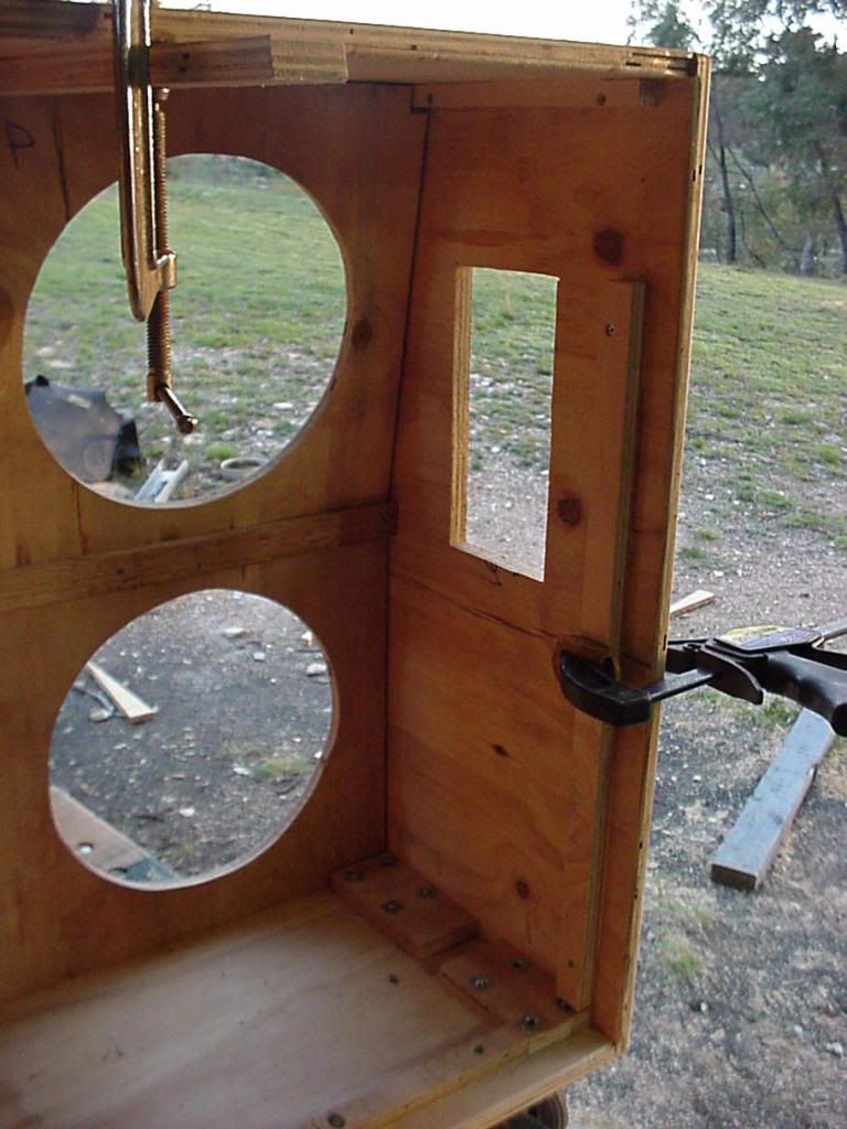
Inside:

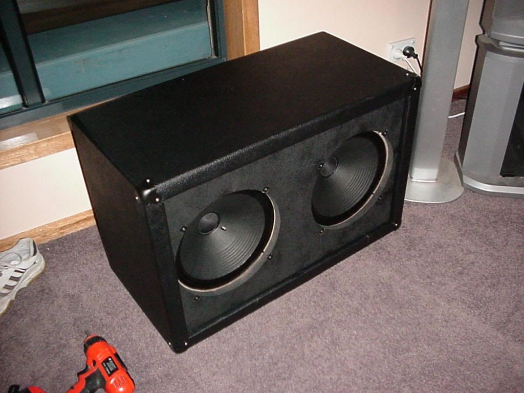
Had enough wood etc left over to make a 2x12 (both 16 ohm speakers):
I will load some totally finished shots (corner rubbers and 'Marshall' logo) later tonight.
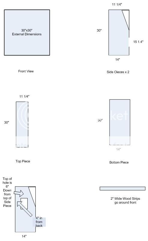
Happy to provide dimensions.
Garry
Fingerjointed the front panel. Never Again...
Greenbacks. Used 4 x 25W 8 ohm. 2 lots of 2 in series (16 ohm), then in parallel, making an input impedence of 8 ohm:
Left input is mono 8 ohm, use both and automatically changes to stereo 16 ohm.
More fingerjoints:
Salt and Pepper grillcloth:
Proper Tolex design:
Gold piping:
Inside:
Had enough wood etc left over to make a 2x12 (both 16 ohm speakers):
I will load some totally finished shots (corner rubbers and 'Marshall' logo) later tonight.
Happy to provide dimensions.
Garry
Last edited:
")