INA217 and the DC-Servo

  • Thread starter Thread starter Ettos
  • Start date Start date
E

Ettos

New member
Hello to everyone!
I was wondering if I can replace the OPA137 (I can't find it!) for the DC output control loop with another FET-input opamp. What do you suggest? Is it good an OPA134? Should I modify the schematic to implement this one?

Thank you very much!
Matteo.

P.S: Sorry for my English...
 

Attachments

  • ina217.webp
    ina217.webp
    18.6 KB · Views: 244
Where are you located? TI shows them o their web site. They even have free samples.... What package is used?

--Ethan
 
Where are you located? TI shows them o their web site. They even have free samples.... What package is used?

--Ethan

Hi Ethan,
I alredy tried to request free samples from TI but they don't ship them to Italy for some unknown reasons... maybe because there are high taxes and tariffs.
The package I need is the PDIP-8.

Thank you,
Matteo.
 
In one of My INA217 2Ch preamps i used a TL072 for the DC Servo (half of the TL072 for each channel) and it worked just fine.....

in my later versions I simply used an High quality output cap(470uF 16v Nichicicon Muse or black gate) or a Output Transformer as opposed to a DC servo to block DC...

I haven"t noticed any audible differance useing a Good output cap over the DC servo and it makes the Design much easier to implement and make for a smaller PCB.....

With the INA217 you really only have any DC offset at the High gain settings and the Input of the next piece of equipment in the Chain most likely allready has an Input cap to block DC.....

Good Luck

Ok, I think I'll use the TL072... but I'm also interested in the cap solution. Sorry for my ignorance but, how do you wire the cap? The "-" of the cap should go to the "Out" of the ina217 and the + to the jack connector?
Thank you!!
M.
 
You just put a Cap in series with the output with the + of the cap faceing the Ina217 and the - of the cap connected to the output....A Good quality cap is needed here and possibly even bypass it with a good 0.1uf poly cap....

Capacitors Block DC But Pass AC so putting a cap on the output blocks any DC from entering the next piece of equipment.....

Cheers

PS: if you are only doing one Channel you can use the TL071...
 
You just put a Cap in series with the output with the + of the cap faceing the Ina217 and the - of the cap connected to the output....

Given that the DC offset should be a very small figure, often you'd orient the cap the other direction and use a 63V cap to block incoming phantom that was erroneously connected.
 
Pcb

Does anybody have PCB drawing for it?

Hello to everyone!
I was wondering if I can replace the OPA137 (I can't find it!) for the DC output control loop with another FET-input opamp. What do you suggest? Is it good an OPA134? Should I modify the schematic to implement this one?

Thank you very much!
Matteo.

P.S: Sorry for my English...
 
In one of My INA217 2Ch preamps i used a TL072 for the DC Servo (half of the TL072 for each channel) and it worked just fine.....

in my later versions I simply used an High quality output cap(470uF 16v Nichicicon Muse or black gate) or a Output Transformer as opposed to a DC servo to block DC...

Hi Minion

In your transformer INA217 version what did you drive the tranny from? Can the INA217 put out enough juice for such a low impedance load?
 
Hi , I really don"t understand either of your questions , Maybe elaborate ??
 
The load on the INA depends on the load of the transformer and the square of its turns ratio. Perhaps you are assuming this is a Neve-style step-up transformer? I would presume it's an ordinary 1:1 line output transformer.
 
I Used a 1:1 Input Transformer , I salvaged it from the Mic section of an old Akai Mixer ......
 
I Used a 1:1 Input Transformer , I salvaged it from the Mic section of an old Akai Mixer ......

Since I am close to having a home again I ordered some IC samples from TI and would like eventually to make a pre using the INA217 that came in my shipment. I also ordered an OPA552 along with it because I plan to use a transformer coupled line driver and wasn't sure if the INA217 could directly drive a tranny. I'll be using one of those Edcor 1:1 units that cost $8.

The spec sheet doesn't have enough info regarding the output current capability or output impedance of the INA217. What I would like to do is have the INA217 drive a switchable 100hz highpass filter and then use the OPA552 for the output driver. But I was wondering if I could go straight from the INA217 to the output tranny if I didn't add the HP filter. The OPA552 has a respectable distortion figure while driving a 600 ohm load but I cannot be certain if the INA217 can do so well with such a load.
 
The spec sheet doesn't have enough info regarding the output current capability or output impedance of the INA217

:confused: 
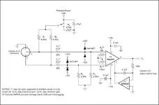
Sure it does, continuous rated at +/-60mA. Given the maximum voltage supply of +/-18V, that's a rather healthy 300 ohm load. Output impedance is likely no more than 100 ohm. I have an INA217 pre laying around I could measure for heavily loaded distortion, this is at a +/-16V supply.

Again, a 1:1 transformer is only a 600 ohm load if it's connected to a 600 ohm load. Into a converter, it's probably a 10K load.
 
Hmm. I forgot this unit was an early prototype that I only had running at 20V. This is a split-rail design using TLE2426, with a 9V battery supply with a DC converter, it gets a bit unhappy with extreme loads, especially this early version. So I imagine a more robust power supply could do better.

Anyway, I didn't have a 600 ohm load handy, so I used my trusty Sony 7506s (63 ohm) instead. The amp also has a 150 ohm series resistor on its output, so that's 213 ohms. I measure almost exactly a 10dB drop at 1kHz at the headphones, which works out to . . . like 0 ohm output impedance. Probably Sony isn't 100% accurate on their spec, but it seems that INA217's output impedance is sufficiently low.

This circuit can do 6.6VRMS at low distortion with the 21V supply (<0.01% THD) into no load, that gets about 2V from the rail, I recall the 32V supply version I have does 10VRMS, which is about the same.

Into 213 ohm, I managed 2.4VRMS at low distortion, for RMS current of only 11mA (peak of 30mA). But at that point, the power supply was sagging down to 36V (from 45V).

Still, worst case based on those results is 11mA, so that's at least 6.6VRMS into 600 ohm. I'll see if I can try that tomorrow.

One consideration is that if you really want to drive an output hard, INA217 is single-ended and you really need the free 6dB from a following inverting stage. I'm not into high headroom anymore, I like very low power consumption and my target is -10dBV input converters.
 
Here is what I came up with for the full version including the Lo-cut filter.

INA Preamp Schematic 37Kb

Nothing original here just stuff copied from datasheets mostly. Grabbed the pad circuit from a schematic of my Toa console. The preamp is intended only for dynamic mics and I will very likely build a pair of them to use until I can get my console and other gear setup again. I wanted to make it with very few capacitors in the audio path so I chose to use servos to null the offsets down to single mV range. Looks promising on "paper" but who can say what gremlins may turn up at the OPT when power is applied to the real deal.

Other ideas I had which I'm too tired to muck with right now was adding a clipping indicator. There's another simple circuit I can copy from the Toa console using two transistors.
I was also trying top decide if it would be worthwhile to have an output level control just before the output driver stage. R7 could be a voltage divider pot instead of a fixed resistor. Pots are an expensive item for me these days so I'm really not sure if it is worth the extra to implement that feature.
 
Honestly, the linearity of that gain pot is going to be terrible with max gain of 66dB, especially if it's not a reverse log taper. Even if it is . . . the gain is going to shoot up 20dB in the last tiny bit of travel. With a pot, you have to choose between a wide gain range and linearity of operation. I feel that the best a pot can do is about a 32dB range (and that's reverse log). So I would think pretty hard about using a 1K pot, or even 500R.

The value of that input pad is huge, like -40dB. 4At min gain of +6dB and headroom of +22dBV, that would tolerate a +56dBV input. Hard to see what the application is there. I'd set it at maybe -24dB and use it to compensate for the reduction in gain range from the revised pot value.

I still question the need for the servo and the output driver. INA217's DC offset is not very high (should be low mV even without the servo), and you have an output transformer that won't pass DC. It will bleed DC offset to ground, but I imagine its DCR is 100 ohm or so, DC should be in the uA range.

I like to see some resistance at the input, 47R on each leg should do. Helps the clamping diodes keep from melting if things get really interesting, and helps to keep the amp from oscillating. I also think it's important to provide some RF rejection at the input, which can be done with inductors, chokes, capacitors, whatever you like.

Since this is a dynamic mic pre I'd provide a switch to drop input impedance to 600R.

Finally, you don't really show what your power supply is other than some filter caps, but if you're going +/-18V it better be strictly regulated as you're right at the max rating for the chip.
 
Yeah the gain control is ugly when you can't afford a fancy rotary switch. So here's one to compromise. Now I have a minimum gain around 30dB and a range switch at the 40dB mark. This should expand the linearity for setting higher gains.

mic_pre-02.gif

Since the gain is going to be 30dB at minimum it now makes sense to have an output level control so I added that in place of R7. I also added 5dB of gain to the output driver so I can get rid of the gain = 1 compensation for the OPA552. And the extra gain won't hurt with mics like the SM7B or Sennheiser 441. Overall gain will be in the 70 dB range which is nice in the event I run across a ribbon mic.

I had the wrong value for the pad resistors before. Now it is set for -20 dB which is much more useful. I added the series resistance to protect the diodes as per your suggestion and some RF bypass caps. If I dig around I may have some 39uH inductors for that purpose. I also put in the impedance switch but not sure if I have the proper value for R20.

The power supply is nice and very well regulated. It is a custom one I built many years ago to power my homemade modular synth. Now that the synth is gone I can adjust the voltage from +/- 15 to +/-18 easily. And there is more than enough current to power two of these peamp circuits. With good grounding technique I shouldn't have any crosstalk. The PSU was designed for a modular synth so crosstalk was factored into it's construction.
 
Looks better. I still think a 500R pot should function adequately without need for the range switch.

On the RF attenuator, instead you want 1nF between inputs and 100pF from each input to ground. Without a cap between the leads, you can actually degrade CMRR of RF due to variance in cap values.
 
Back
Top