How to Ground an old Tube Amp

  • Thread starter Thread starter renton
  • Start date Start date
R

renton

New member
Hi...hopefully some electronic know-it-all's could be of some assistance for me today!

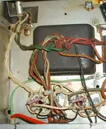
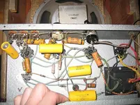
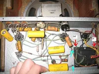
I have a really old no-name tub amplifier (probably 60's home-made). It's a 2 prong plug. It has 2 instrument inputs and 1 mic input with a volume and tone knob. When I use the electric guitar it's fine unless I touch a live microphone, or if I touch the strings of someone else's guitar that's pluggin in all parties involved get a nasty shock. Or similarily if someone else playing a guitar were to reach over and touch my strings while their other hand is on their own guitar's string they'll get a nasty shock.

So I'm just wondering if there might be an easy soldering job to maybe put on a 3 prong plug to ground it out so one could at least sing into a mic while playing guitar through this amp without burning their lips off!

Did they just NOT ground older electronics or what's up with that? I'd figure it would be kinda useless if you couldn't touch any metal while playing through it...maybe I'm missing something here!

any help would be appreciated...
thanks
 
It's hard to T.S. anything without looking at it first hand but I can give you some educated guesses. All inputs to an amp are terminated with a resistor to ground and then to a coupling cap to the grid of the input amp. It sounds like you got a difference of potential between the grounds which would indicate a lifted ground on one or probably a dirty corroded input jack. Another possibilty is the coupling cap is shorted which would put grid voltage directly to the input.

At any rate the standard procedure for an old tuber like that is doing an emissions and short test on the tubes and replacing all the electrolytic capacitors. Look for visual signs of overheating or burning esp on the resistors. The filament wires (if I remember right are green) are twisted and should be routed next to the chassis The b+ or plate voltage wires are red or red traced and shouldnt have any bare spots or signs of overheating. The high wattage or big resistors should be ohmed out and replaced if they are over 10% out of tolerance. All of the input jacks should be cleaned and unless they are gold or silver plated (yes things like the Tektronics scopes are assembled with silver solder) anything can be used.. Also the pots (controls should be sprayed with a contact cleaner.

Anything beyond that requires a signal generator and scope to analyze the gain and freq response . Also a tube spec sheet with the voltages on the control grid, accelerator grid, suppressor grid and the plate under idle conditions if it needs furher troubleshooting. The ones that might be critical are the grid and plate voltages. Those are just a few off the top of my head.....
 
It has 4 tubes and I can see on 2 of them that one says "6V6" and one says "5Y3" Pardon my inaccurate terminology now...but on the two instrument input jacks, there are 2 leads with connections. One connection has a resistor going to a lead on the first tube, while the other connector has a resistor and a huge capacitor going to another lead on the tube, but also it is attached to a long wire that runs across all 3 input jacks as well as both the volume and tone pots...one end of the power chord connects on the final connector of the tone pot at the end of the line. The other end of the power chord goes to a lead on the 4th tube.

I have no idea if that means anything!! But you guys definitely know more than myself...so maybe that long wire that solder's onto lead's from all the jacks and pots is a ground or something...but one end of the power chord already attaches to that..so I'm not sure...

thanks!
 
Just hook the ground wire to the chassis. Pick a screw on the back of the amp that goes into metal and attach your ground wire to that. That ground wire on a 3 prong plug, is there to take any shock from the chassis, which you can touch, and give it a path ground, so the shock doesn't go through you. So just hook the wire to the chassis somewhere, that is where it is suppose to go.
 
you sure it's as basic as this? I've already thought of that idea...but after some research on the web I've seen that grounding in amplifiers is a little more involved than that...but if that will work I'd be happy!
 
It is not just as basic as that. Have a tech do it. He will replace your two pronger with a nice three prong cord grounded to the chassis. Arcaxis has the best advice, basically there are a couple ways to do it, depending on the amp design. A tech will be able to hook it up so that there is no AC on the chassis, which is what happens when you plug the thing in the wrong polarity with the two prong plug. You don't notice until you touch another ground source, like a person or mic. Karyoker's advice concerns faults and problems, and isn't really concerned with actual amp A/C grounding schemes. If the amp works fine, it's definitely the grounding of the A/C you need to address.
BTW just hooking up the third wire (which you don't have anyway) with a screw is absolutely not acceptable for grounding a/c line voltage. A/C line voltage grounds should always be soldered to the chassis. Using a screw can lead to a poor connection due to corrosion or loosening from vibration, and that's as bad as what you have now. Or worse, since you will think it is safe.
 
renton said:
you sure it's as basic as this? I've already thought of that idea...but after some research on the web I've seen that grounding in amplifiers is a little more involved than that...but if that will work I'd be happy!

Yes, it is just as easy as that. I have been a tech since the mid 70's and it has always worked for me. Boingoman is also correct when he says that when you replace the 2 prong with a 3 prong, you do need to watch the polarity.

You know, electricity is not a mystery. People are generally afraid of it because it can hurt them, and they don't take the time to understand it. If you just follow some simple rules, it won't hurt you. When working on it, make sure it's unplugged. Only ever use one hand. If you use 2, then electricity has a path through your body. I will guaentee if you take it to a shop, they will unsolder the 2 connections, and put the new plug wire in its place and screw the ground to the chassis. I know this because I have done it 100 times.
 
okay cool, but is there any way to ensure you keep polarity the same if replaceing a plug with a 3 prong? Everyone's been very helpful, I appreciate it!
 
juststartingout said:
Yes, it is just as easy as that. I have been a tech since the mid 70's and it has always worked for me. Boingoman is also correct when he says that when you replace the 2 prong with a 3 prong, you do need to watch the polarity.

You know, electricity is not a mystery. People are generally afraid of it because it can hurt them, and they don't take the time to understand it. If you just follow some simple rules, it won't hurt you. When working on it, make sure it's unplugged. Only ever use one hand. If you use 2, then electricity has a path through your body. I will guaentee if you take it to a shop, they will unsolder the 2 connections, and put the new plug wire in its place and screw the ground to the chassis. I know this because I have done it 100 times.

LOL. Yes, I guess it is that simple, as long as...

You observe the correct polarity.
Use a ring terminal on the ground wire, if you screw it to the chassis. And lock washers and locktite.

I still prefer soldering to the chassis for modding an amp that wasn't grounded originally. It can be hard to find a suitable existing point for A/C ground and I prefer to not drill holes in a vintage chassis if I can help it. The same when I do other A/C mods. I try to make every mod so the amp can be returned to it's original state.
 
Everyone here has the right idea. The chassis can be grounded via solder or a ring terminal crimped AND soldered to the ground conductor. You should never use bare wire to connect a ground. If you like, I can do this for you for free if you just pay shipping to and from me. Ill give you the cord, do the job, and clean your controls and switches as well as go over the parts and replace any electrolytics that need replacing and correct any soldering issues. I'm in Columbia, SC area code 29209 if you want to check shipping rates. PM me for more info.
 
boingoman said:
It can be hard to find a suitable existing point for A/C ground .
Don't make a tragedy from this... :) .
A guitar amp isn't a RF unit that requires THE lowest noise grounding point,the one you can find only with a scope and a box of Prozac. :D
Take a look at this Fender Bassman 100 grounding:the green-yellow wire (cable ground) goes to one of mains power tranny's screws.
And that's about it. :) The amp in question is dead silent.
Of course,for a little variation,you could other PT's screws as well... ;)
(..sorry,but I couldn't resist on that!:):))
Regards,
 

Attachments

  • Ground.webp
    Ground.webp
    22.9 KB · Views: 348
okay, I've got a picture here of the inside of my amp...I figured since everyone here is very knowledgable and extremely helpful (very kind offer producerkid), before I got and solder on my cable I bought, I'd let you look here and make sure I'm cool with just replaceing the hot and neutral wire's with the new ones and soldering on the ground to the chassis.

I quite honestly can't afford a penny for a tech to look at it, so I have to do this myself...I'm pretty high up on the common sense scale, so I'm confident I'm not going to do something stupid (I have basic electronic's knowledge). But looking at this picture, I'd like to know maybe what you guys think would be easiest.

thanks again for all the help! I love this board!!

power cord comes in on the top right...the input jacks are 1, 2, and 3 on the top left...then volume pot and then tone pot.
 

Attachments

  • amp 001-2.webp
    amp 001-2.webp
    49.1 KB · Views: 199
OK,I drawed for you two possible options (1st and 2nd,marked with red arrows).
The ground wire's end should be soldered to a ring terminal,as you can see on the Bassman's picture I posted.The only difference between your amp and that Bassman is that your amps' mains tranny gets through a narrower chassis hole and the bell end is mounted afterwards.
Unscrew one of the washers of the mains transformer's screws (choose the one wich suits you best for your layout...but first option remains the best) and put the ring terminal,then screw back the washer firmly (but be careful not to f%#& the screw!).
The ring terminal MUST stay right under the washer because the chassis and the mains tranny's bell end are painted and there's a big risk to have a poor ground contact if you put it (the ring terminal) inbetween.
Also,I suggest you to do the same with the other two ground points I see in your picture (the ones marked with blue arrows) for the same reason.Unscrew these washers ONE AT THE TIME,mount the ring terminals as I said and you're good to go!
Good luck,
Le Basseur
PS
...by the way,I just love that Alnico driver! :)
 

Attachments

  • amp 001-2.webp
    amp 001-2.webp
    50.1 KB · Views: 210
thanks guys...my question is why can't I just attach the ground to the chassis by itself...why do I have to move the neutral to the "power-switch" (which I'm guessing is the black square on the right...it's a transformer of some sort...there's no actual power switch on this amp...plug it in and she goes). So yeah...why move the neutral line instead of leaving it on the that tube lead it's on now.

Also, Le Basseur, I'm not sure about the ground points you're talking about (the blue arrows in your picture)...because I don't know if you can see in my pic, but those capacitors actually solder onto a little metal swing hinge type thing that's UNDER the corner screw that you're suggesting my option #2 could be. The top left screw threading. Basically I mean they're not just soldered to the metal chassis...they are attached to the corner's of the black transformer.

arcaxis...I figured I'd just tie the cord in a knot past on the one side of the case...so it can't pull through and if it does get yanked it pulls on the knot...and NOT the soldered wires. My chord has black, white and green...and my plug end has silver, gold, and green...I'm recalling that white=silver, black=gold/brass and green=green....anyone want to tell me different before I plug it in???:)
thanks...
 
Thanks arcaxis for being faster than me.
My last 24 hours were hell,I mean HELL and in this right moment I arrived home.
Everything that you said about renton's amp is correct.
Regards,
 
Back
Top