O.K Guys,
RE: The cable schematics. I scanned three seperate items but I can not figure out how to merge them into one document. I have not any any formal PC training and it is lots of trial, error and the ocasional success. So here is the deal.
There are two cable schematic attatchments; the first one has three schematics one of wich covers converting an unbalanced instrument cable (1/4") to an XLR balanced jack. This can also be converted to a TRS with the Tip = Hot, Ring = neutral, and Sleeve = ground. On the XLR as seen in the diagram MOST equipment should be wired as Pin 1 = ground, Pin 2 = Hot and Pin 3 = ground HOWEVER some equipment has been manufactured with Pin 3 = Hot and Pin 2 = Neutral.
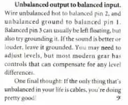
There is also a text document on how to wire an unbalanced cable to a balanced cable stating pin three on the XLR can usually be left floating but in some equipment, grounding pin 3 will sound better. So I suppose you would have to make a one of each to see wich way works best for you.
The other schematic attatchment is a diagram to make an XLR patch cable a "ground lift" cable for equipment that may not have a ground lift or you can take an existing XLR cable and snip the ground.
None of these are the original article I remember reading about the "unidirectional semi-balanced" I'm afraid; but I will keep looking for it.
Scott
")