Homebrew pickup winder

  • Thread starter Thread starter JCH
  • Start date Start date
JCH

JCH

El Nacho
I looked at quite a few different winder designs before I built this one. It's was my first attempt at one of these. The mainshaft is driven by a roller on to the 5" wheel on the right side (when viewed from the front), which in turn drives the other 5" wheel at a 10/1 ratio to the mainshaft for the counter. It only counts every tenth turn. I did this to keep the cyclic rate down low enough to use a cheap proximity switch like those used for home alarm systems. I wrapped the shaft with electrical tape to get the proper diameter, and calibrated it it by trimming the tape about 1/8th inch at a time I was able to to get it accurate within a couple of turns per thousand. The counter itself I made out of a pedometer. They have a small inertia switch inside which triggers the step counter. I removed the switch, and soldered my leads to the contacts.

My goal was to build it cheaply, and out of things commonly available at a hardware store. Most of the winders I looked at utilized belts and pulleys that weren't readily available, so in a rare epiphany I had the idea to use a capstan and roller versus a drive belt, and it worked out great. Along with helping to keep the unit compact, it really simplified taming the 10,000rpm sewing machine motor to usable speed with plenty of torque.

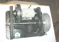
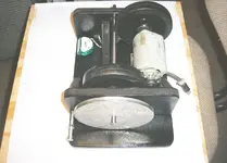
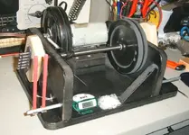
The mainshaft Is a 3/8" rod supported by cheap cage bearings. The motor is mounted on a common door hinge that I cut down to fit. It's positioned so that only the weight of the motor leaning on it is what drives the 5" wheel. The other wheel is for the counter only. It leans on the mainshaft where I built up the diameter to 1/2" for the ten to one ratio. I mounted a small alnico rod magnet on the counter wheel to trigger the switch.

I had to do some fine tuning to the drive wheel. It was a bit out of round. I fixed that by truing it with a sharp scraper. Once it was complete I balanced it by drilling material away from the roller wheel. It turned freely enough that it was obvious where I needed to remove weight because the bias would find bottom.

I power it with my variac.

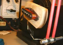
The wire guides are allthread wrapped with shrinktube threaded into little locking collars. I cut a screwdriver slot onto the end.

The white thing next to the counter is a felt pad with talc on it. Yes talc.:facepalm: I put it on my fingers that guide the wire.
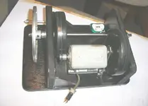
 

Attachments

  • windr 004.webp
    windr 004.webp
    24.3 KB · Views: 343
  • windr 005.webp
    windr 005.webp
    33.9 KB · Views: 338
  • windr 007.webp
    windr 007.webp
    29.8 KB · Views: 330
  • windr 010.webp
    windr 010.webp
    62.7 KB · Views: 334
  • windr 012.webp
    windr 012.webp
    36.4 KB · Views: 333
That looks close to the Jason Lollar unit that he explains in a book he wrote and sells. But yours looks simpler. Hmm. Maybe you should share your plans? :D
 
Thanks JCH, I shall post a thread about mine as I'm building it. I have spent a bit of time getting some parts together and will be knocking up mark 1 this week hopefully.

I like the solid drive wheel approach. not seen that before.
 
Thanks JCH, I shall post a thread about mine as I'm building it. I have spent a bit of time getting some parts together and will be knocking up mark 1 this week hopefully.

I like the solid drive wheel approach. not seen that before.
Another alternative for a counter is a bicycle speedometer. It's possible to calibrate them to a 1 meter wheel circumference, and to read out in meters traveled.

I've been gathering parts for a new winder for a while. I want to build one that automatically guides and tensions the wire. I plan to use the automatic line leveling device from a spinning reel to actuate a cable. I've got an idea how to easily make the winds per layer, and length of travel variable. I built an optical counter switch for it already. If you want the schematic and a picture I'll post it up.
 
My old winder used a pedometer and I've tried the calculator approach but non seem to work at decent rpm. I'm getting a few medical standard reed switches today and if they are no good it's time to look at some light interruption options.

Not sure if you are familiar with this site. There is a wealth of really knowledgeable people there. I'm going to post up some pictures of mark 1 later today but in the guitar and bass section as it's really allied to the HR Design and build.
 
My old winder used a pedometer and I've tried the calculator approach but non seem to work at decent rpm. I'm getting a few medical standard reed switches today and if they are no good it's time to look at some light interruption options.
It's not the fault of the counter, but rather the unreliability of reed switches at high speeds. That's why I used the decade wheel for my counter. The optical switch works great at high speed, but you'll need a real counter that triggers on pulses.

Not sure if you are familiar with this site.
Oh yeah, I've been a member there for years. I don't get on there too much lately. Many of the pro's who used to post there aren't around any more, and they've been replaced by others that don't have as much to offer. It's still good, but nothing like it was.
 
It's not the fault of the counter, but rather the unreliability of reed switches at high speeds. That's why I used the decade wheel for my counter. The optical switch works great at high speed, but you'll need a real counter that triggers on pulses.

Oh yeah, I've been a member there for years. I don't get on there too much lately. Many of the pro's who used to post there aren't around any more, and they've been replaced by others that don't have as much to offer. It's still good, but nothing like it was.


Thats the way I'm heading. The reed switch works well now up to about 750rpm as I've added some passing plates but still not what I want. Accuracey has been my byword for as long as I remember. I'm fussy about tools being right.

Posted my mark 1 up in the g&b board just now...
 
I've been gathering parts for a new winder for a while. I want to build one that automatically guides and tensions the wire. I plan to use the automatic line leveling device from a spinning reel to actuate a cable. I've got an idea how to easily make the winds per layer, and length of travel variable. I built an optical counter switch for it already. If you want the schematic and a picture I'll post it up.

I built the new winder. :)


I built the new winder. :)


Just picked up on this mate. Missed the post for a while. Thats pretty cool. I'd like to do something similar. Any detail on the tensioner as I'm thinking that would work on my winder.
 
Just picked up on this mate. Missed the post for a while. Thats pretty cool. I'd like to do something similar. Any detail on the tensioner as I'm thinking that would work on my winder.
Thanks Man. It works pretty well.

Hillbilly Engineering to the rescue!
I made it mostly out of crap that I had laying around. It's all original. I haven't seen another like it. The rate of the traverse is fully adjustable, and fully synced. The length of the traverse is also adjustable 1/8"-3/4" Both of these aspects are unique to any home built mechanical automatic winders that I've seen. Most machines require a different cam for every different coil design. Here's another vid that shows the whole machine a little better.

The tensioner was something I didn't give much thought to until I couldn't do without one. On my initial experiments with the machine I was tensioning by hand. After that I tried a piece of felt folded in an alligator clip that I had rigged with a small screw and nut for adjustment. That worked, but wasn't very reliable. The little C-clamp, and self adhesive felt pads were stuff that I had on hand. Someone on the pickup forum suggested using a simple dancer to regulate the tension.

I made it from a bronze .056 string, and a crimp-on eyelet. I de-burred, and polished the eyelet so that it wouldn't abrade the insulation of the wire then soldered it to the guitar string. It oscillates with the rotation of the bobbin, and holds even tension on all surfaces of the coil. You can actually see the tension by watching the deflection of the dancer. Because of this, the pickups will be less microphonic than those tensioned by hand. I don't like to pot humbucker's unless I have to.
This will help the cause. :thumbs up: I'd recommend giving it a go.

I plan on adding one to my hand winder. It will be nice to only have to worry about guiding the wire.

Notice that I'm using the frequency counter on my DMM as a tachometer; 20hz = 1,200rpm. Keeping track of all data makes it possible to accurately reproduce.


These are looks nice. Good work. Keep doing!
Gracias.
 
Last edited:
Back
Top