Balanced line driver (DRV134) and noise

  • Thread starter Thread starter Ettos
  • Start date Start date
E

Ettos

New member
Hi all,
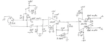
I'm building a microphone preamp based on an INA217 chip.
I'm trying to get a balanced output with the DRV134 driver. I just followed the drv134 datasheet schematic (see the attachment) but I'm getting a lot of noise (a sort of white noise).
The output of ina217 is pretty quiet, all the noise is generated by the drv134.
I tried to remove C4 and C5, and to use different bypass capacitor but... nothing!

Is there anything I can do to solve this? Do you suggest other solutions to get a balanced output?

Thank you very much,
Matteo.
 

Attachments

  • drv134.webp
    drv134.webp
    25.5 KB · Views: 5,342
There are other ways to get a ballanced output , some much easier that a DRV134 ....

There is the output transformer route , Expensive , but easy and you can drop the DC servo when useing an output transformer .....

You can use a Unity gain inverter to get the -minus output for the Ballanced output , You can do this with an opamp , this is the route I went when I made my first INA217 preamp ....

Then there is impedance ballanced which can be done with a couple passive components ......


Cheers
 
perhaps it's a layout problem... inter-element capacitance..
 
Let's start by defining your absolute noise level. Whatever your test device is, you need to calibrate it so when you have a given AC voltage you know what it is. INA217 output should be -98dBV or so. That should also be the noise of DRV134. That will sum to -95dBV-ish.

Now, remove INA217 from circuit, and ground the DRV134 input. What is that noise level? If it's properly quiet, reconnect INA217. How many dB did the noise go up? Try INA217 by itself, and also with servo. Any difference?

If no answers there, try a different DRV134 chip, maybe yours got toasted. Check DC voltage at every IC pin, make sure they are all correct. Measure current from your power supply, should add up to the total quiescent draws of all three chips. If anything is amiss, investigate.

As far as other solutions . . . well, I realize the temptation to go overboard on TI datasheets, but is all that strictly necessary? What is the goal of the output? What length of cable are you driving? What is the CMRR of the receiving amplifier? If it's only 50dB, then the DRV134 is kinda silly. An output transformer/input transformer will kick the crap out of nearly any IC scheme, in real life if not on paper, but transformers do have their limitations, and good ones are extremely expensive. I like the $0.02 solution of a resistor myself . . .

And what about all the stuff that isn't in your schematic, but can really help in real life? I find that ICs getting toasted by patchbay errors where phantom is present is a LOT bigger problem than CMRR of carefully balanced active outputs vs. simple impedance balanced output schemes, but I see no protecting diodes, nor resistors, nor capacitors on the outputs in your design. That includes the inputs of INA217, I would protect that from phantom surges, and quickly. I don't know how sensitive DRV134 to surge currents on its outputs, but that would concern me too.

Oh yes, I know, capacitors are bad, of course. I'd bet if you placed a decent, properly sized output cap on one channel you couldn't blindly spot the difference between channels--you already have caps in the circuit anyway.
 
Back
Top