I've gotten a few questions along the way so I thought to add a bit to this old thread. I went back and forth on whether to use a 3 voltage JLM regulator board or to breadboard a power supply. The MP-2 board includes onboard voltage regulators so you do not NEED to regulate incoming + and - rails. The +48 phantom does need to be regulated.
As I recall the onboard regulators output voltage is +-24 volts so you should feed at least +- 27 volts so as to allow the onboard regulators to do their jobs.
I ended up bread boarding a power supply that has unregulated +- 34 volts and regulated 48 volts. You can use the schematic for the JLM power supply as a starting point if you want to do it that way.
If you you use the JLM PS you could set the +- rails to almost anything between 27 and whatever the PS will output. Don't put is so high so as to not be regulated at all. (Short answer: set to +-28v)
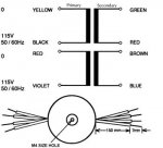
THe toriod I used is an Amveco 62075 which has dual 22v secondaries. You can find a wiring diagram to the transformer here :
AMVECO, INC: Miniature Low Profile Transformers
In my case I wanted it to run on US power (115v) so I wired the primaries in parallel. Black ad Violet were wired together for on of the 115 volts leads and Red and Yellow were wired together for the other 115 volt lead. Don't swap any of the wires as that would place the 2 primary windings out of phase with each other and may let some of the smoke out.
The 2 secondaries are wired in series. Blue is one voltage lead, Green the other voltage lead and red and brown are tied together to make the center tap lead.
You might ask how it is that I am getting 34 volts DC out of 22 volt AC windings. The answer is that the 22 volts is RMS which is 0.707 of the peak to peak voltage. (so 22/0.707 = 31.1 v and not 34) And our house voltage is closer to 125 v than 115 v.
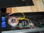
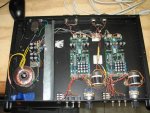
Here is a photo or 2.


