Deluxe Electric Mistress

Neve1073lover

Inset French Saying Here
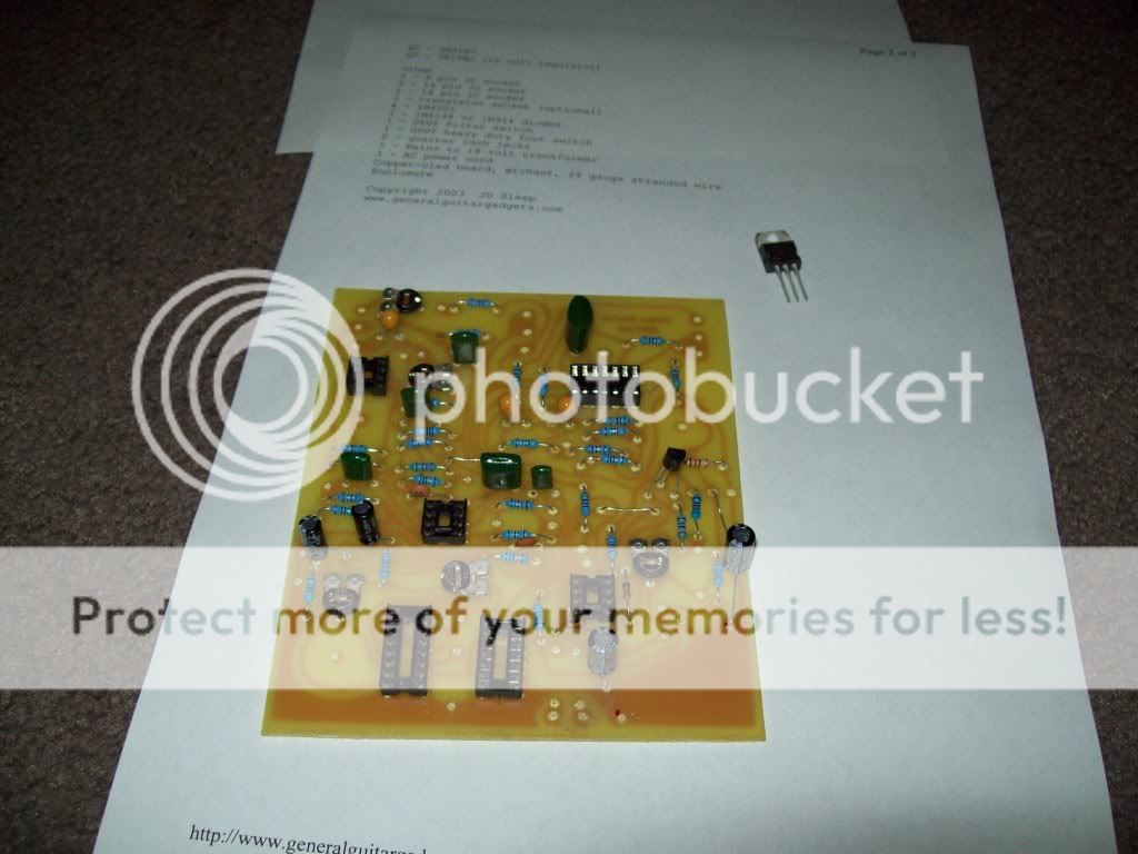
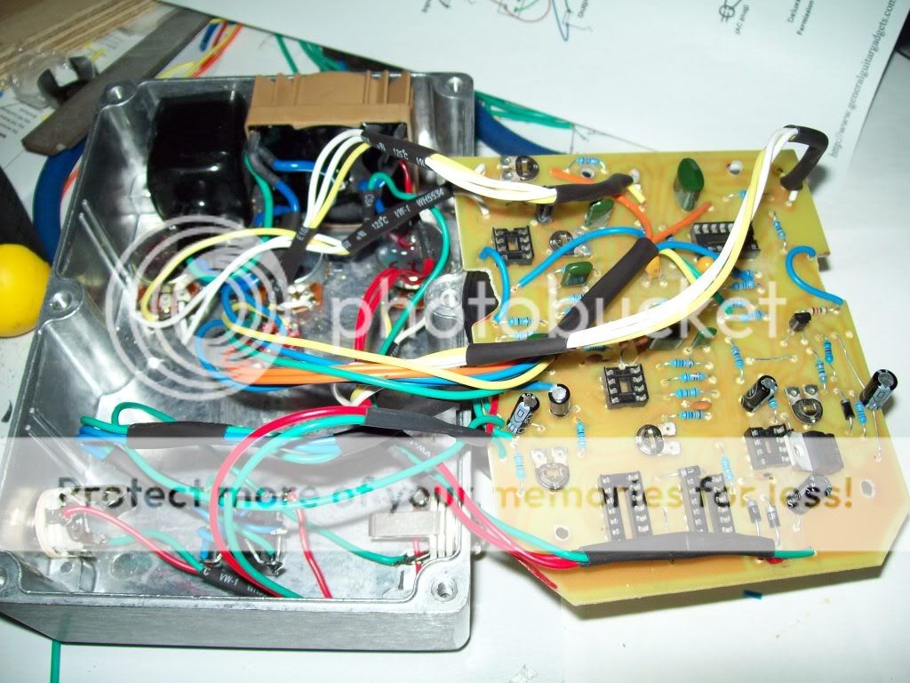
Next project from generalguitargadgets.com

Wanted to try UV pcb board manufacture.

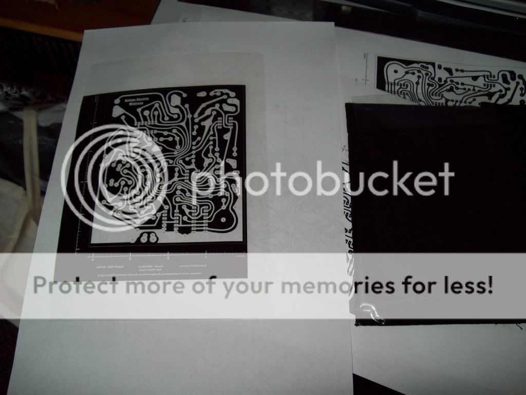
Step one is to create the NEGATIVE design on an overhead film. I tried just printing from the pdf from the website but it seemd to scale to a very large picture. Copied it into MS Word and scaled it by printing and measuring the printout (there are inch scales on the pdf)..

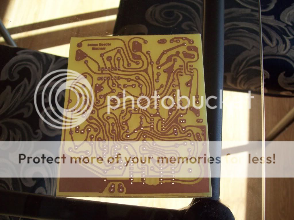
Step 2 is to use a UV light for 3 or so minutes to 'set' the pcb tracks.
I taped the plastic on. Get it very flat onto the pcb for best results. Some people use a thin glass sheet over the top.

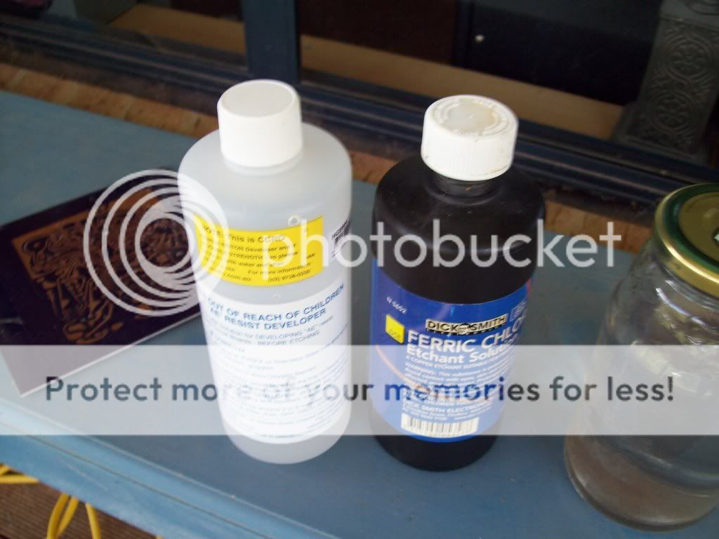
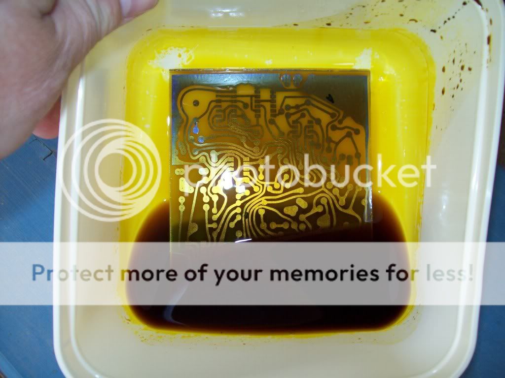
The clear parts on the overhead (for the type of UV pcb kit I am using) remain after you use the 'AE' resist developer. Took about 2 minutes to take the exposed plastic off the copper pcb.

Photos and more soon.
 
The PCB Etching

The overhead negative:

100_0637.jpg


The Resist Developer and Ferric Chloride etchant:

100_0638.jpg


You swish in the Resist Developer until all of the areas to be etched are bright copper colour.

Then into the etchant. When it goes very dark, pour it out and replace:

100_0640.jpg


When all copper taken off (that should be taken off), wash off with water.
Drill the holes and then use the resist stripper to clean off the plastic covered tracks ready for soldering:

100_0641.jpg


Look for shorts (I had one) and get ready to stuff the board.

Garry
 
Stuffed Board

Only a few components missing:

100_0643.jpg


I had to work out which direction the 7815AC faced.

Looking at the 'dmistlo.gif' diagram (and in the pic above), it faces towards the right.
ie pin 1 (input) is towards the bottom of the diagram/picture.

Wires on tomorrow.

Finding an SAD1024A is a problem. They are very expensive. Have some quotes coming.

Spent about $50 so far (already had the UV pcb makings).
 
Wires on and Started Enclosure

I wanted to fit everything into as small a box as possible.

Found a box, but needed to do some minor changes to the pcb. Cut off a track, so put in a jumper on each side of the pcb:
100_0654.jpg


Found a toroidal 18V transformer that would JUST fit. Mounted the pcb to the top plate:
100_0653.jpg

Garry
 
Power Supply Installed

Shrink wrapped everything and put a plastic cover over the 240V wires.

Earth is in between the power connector and the transformer.

Just connected to the pcb so I can check voltage runs and ensure that there are no shorts to audio circuit:

100_0655.jpg
 
Found a pcb Error

I have been testing the power circuit prior to connecting any other wires.
Found I had a short between the D1/D2 pads and R21. Could not see a short, but running a knife between the pads fixed it.

Then went and tested every IC pinout to earth, looking for unnexpected voltages.

Found no voltage at pin 5 of IC5 (LM311). The layout gif shows that it should be connected to pin 6, then pin 8.

Then checked a schematic that showed that pin 5 should be connected to 6.

The pcb design just has a pad. No connection at all. Soldered together and that was all for today.

I will drop message to generalguitargadgets.com. Who can you trust these days?

Also you should note that you need to have a centre tap on the transformer.
 
You Must Use LN4001 Diodes

I could not source LN4001 diodes so I tried LN4004s.

They cause too large a voltage drop for the MC7814AC voltage regulator to work.

The spec sheet for the voltage reg says that the Vin must be 2V higher than Vout. Therefore must have at least 17V at Vin.

I am getting 15.75V at Vin by using the LN4004 diodes.

Now trying to source LN4001 NOS. Could be a while.
 
All Connected Up

While I wait on 1N4001 diodes (still looking...), I have connected up all of the wiring.

100_0656.jpg


Thought I had found a reasonably priced SAD1024A, but they are out of stock... :mad::mad:
 
50th Post!

Woo Hoo.:D:D
Have sourced 1N4001 (x25 and 25 of all other values from 1N4001 to 1N4007...) Only way I could source small numbers, though Radio Shack has them in stock in the US.

Cannot find a cheap SAD1024A. Cheapest is $100US! Other venders have large minimum orders. I can buy a genuine Mistress for not much more!

May take a while to find a cheap one. Wish I had known this before I started.
 
Last edited:
Found a 'Cheap' SAD1024A

Been looking for a while and getting quotes. Some places are asking $200US! :eek:
Most places make out they have them but don't when asked for a quote. Big waste of time.

Found a place in Germany that has some stock and actually had a price.

So SAD1024A is on its way at a cost of $120AUS delivered.
 
Installed the 1N4001 diodes and no actual difference in voltage drop to the 1N4004's.

The spec of the voltage regulator says minimum 17V.

Installed a 2x12V toroidal trans and getting 21V at the regulator input and 14.9V at the output. The regulator can take from 17V to 30V so 24 volt trans (delivers 21V) is in spec.

Still waiting on the SAD1024A chip....
 
Last edited:
The tyranny of distance really gets to me when I wait so long for an item from O.S. to find it doesn't work, fit etc.
I feel your pain!
Fingers crossed it's just a minor hiccough!
 
Hacking the Electric Mistress

Yeah I got a board from General Gadgets a few years ago and put it together and it didn't work and then it sat....story of my life!

Any way I finally put it back on the bench and began to get into it deeper. Found a good link for making a testing probe at : Testing Probe

Good call on the missing traces on LM311 5,6 & 8.

When I built mine i got "the" chip from Small Bear. I got it pretty cheap, so maybe that my problem. It appears to be a SAD1024A except my chip says:
RETICON SAD1 024A ...not the space between the 1 and the 0. I think its the same, but no real way of telling.

After testing with the probe I found a bad solder joint and finally it would pass signal when the effect was engaged. However I still do not get any real effects yet. Depending on the Fiter/Matrix switch I can get some oscilations with the range switch but that's it. I cannont seem to get any output from pin 12 or 6 from the SAD1024 which is what feeds the effected signal to the output so I'm think the SAD1024 may not be what it appears to be.

Any further progress on you project?
 
The Voltage drop for all Standard silicone diodes are going to be the same at o.7v , if you can source a germanium rectifier diode it sould only have 0.3v voltage drop......

Good luck
 
The Voltage drop for all Standard silicone diodes are going to be the same at o.7v , if you can source a germanium rectifier diode it sould only have 0.3v voltage drop......

Good luck

I upped the voltage to 24V (new toroidal Transformer) and have not gone any further. Sitting on the bench....
 
Back
Top