Tascam 388 Anomalies

LUNE

...a pieds joints
There are two different issues here. In practice I COULD work around the first (though it’d be nice to fix ‘er up right) and the second is rather more of a handicap in practice.

Issue #1:
Track 5 meter does not read on record function enabled (red light on track 5). So no monitoring of input regardless of what channel is used to assign to track 5. The actual input does work on both Line & mic in (channel 5) and I can record on track 5 fine enough (assigned from whatever channel). The VU meter does show signal on playback AND IT CONTINUES TO SHOW LEVEL ON TAPE EVEN WHEN THE TRACK 5 RECORD FUNCTION IS ENGAGED (which is when it should be reading the line/mic in).

Should I be looking on the Channel Rec/Play PCB boards? or could this be something in the record function section? Am I correct in my assumption that this would have to be an actual problem on a PCB board somewhere (dead Capacitor etc.) NOT just a mis-adjustment somewhere?

Issue #2:
Both the Aux & Effect outs produce a sort of muffled ‘oil in a frying pan’ sound. Maybe about 3-5 "plips" per second and erratic (not regular). Not terribly loud, but certainly problematic. I’ve heard this sound on some other old questionable mixing boards before – is this dead/dying capacitors somewhere, or something identifiable from this sort of sound? The sound is coming out of the AUX/EFF outs regardless if there is any AUX/EFF sent from the actual channels, but the master AUX/EFF has to be giving something out (so when I turn down the Master AUX or EFF all the way, the muffled frying pan attenuates. (just to be clear, sound DOES come out of here as well along with the muffled frying pan noise, again is not TERRIBLY loud, but it comes through.) I didn’t see anything obvious like an “AUX/EFF out” PCB board – should I look on one of the motherboard PCBs? Anyone have ideas where to look here?

Thanks for any input.
 
Hi lune...

For issue#1:

I'm probably not going to be as much help as someone who has a 388 and the manual to reference, but it kinda sounds like there might be a relay or some other switching component that is stuck in one position, somewhere in the record circuity for channel 5. It seems like whatever switches the signal source going to that meter is stuck with the source always being the tape, not allowing you to see the mic or line on the meter.

If you have the schematics, try following the signal from the meter backwards to whatever switches the source signal that is sent to it. That might be your suspect. I'm a total beginner at fixing this stuff... But that's where i'd start. Hopefully someone with more experience can chime in...

For issue #2:

When i first got my M-520, i had a few inputs that had those exact same symptoms. Some channels had noisy mic inputs, some had noise in the line or tape inputs. There were enough channels with noise, that, i decided to go through them all and replace the old capacitors. After recapping all the channels, the noise and pops were gone. So it's pretty likely that what i was hearing were the old dying capacitors.

If the noise is still the same regardless of which channels are sending to the AUX, and the AUX master fader attenuates the noise, then i'd suspect the bad caps or cause, is somewhere in the AUX master circuitry. I'd give the manual a look and see what PCB that stuff is on.

Those are my first suggestions... Hopefully it helps a bit. Do you have the service manual for the 388? I find my self going back to my 520 manual all the time. :)

-Tom.
 
hi Tom, thanks for the input and the sound advice.

for issue #1 (vu meter not 'switching'), your "switch/relay" idea seems plausible and would lead me to guess on checking out the "monitor pcb ass'y". (I'm almost there , not quite...)
maybe something in the record enable button switches this, but this still could be other things. my overall guess is that it would have to be either the "monitor pcb assy" or the "meter amp pcb assy" (I've looked at this and not noticed anything visually obvious) - I'll get to the "monitor pcb assy", its just a little intimidating at the moment.

about issue #2 (muted-oil-frying-pan-noise on aux & eff outs) my guess is the problem would have to be in the "bal amp pcb assy" or one of the "bus pcb assy" (I would have guessed more likely in "B" (the one with the gain nobs) than "A" (the one with the pan nobs)). I've pulled all of these out (I think I rather enjoy putting these multipin connectors back in place over pulling them apart...) and don't see anything jumping out at me. I didn't think I'd be getting this deep with this machine at all, but here we go... I have a better understanding of where everything's at anyway. there sure is a mess of cords in there, i'm glad they've got their color scheme going.

so Tom, did your caps have visual clues that they were off, or at the 'just making noise point" they are perhaps just beginning to fail and have no visual signs? if this is so, maybe sweetbeats has the right idea with recapping everything from the getgo. in any case I don't see anything obviously wrong with the caps I'm looking at - no bulging or leaking. once in a while there is a black mark on a cap here or there, it looks like someone marked it with a sharpie or some paint. anyone know what this is about? is it some manifestation of cap failure, or is it what it looks like, which is that it was marked with a paint pen of some kind for some reason? I've got a picture here, but its basically worthless - I can't take these small clear pictures I see people posting here with the camera that I've got...
black painted capacitor.jpg
black 'painted' capacitor is just about center of picture.

I really wish there would be a way for me to get away with replacing as few caps as necessary, there's something like 32 on the "buss pcb assy B" alone:eek:. I also wish there were some way to check caps without getting them off the machine - when I invent my own universe, you'll be able to check capacitors on the pcb board!:rolleyes:

and in fact, I have to admit, I'm a 'recapping' virgin. and a little nervous. I'm sure going to get a better soldering gun before I get into this and maybe make some practice somehow on something else.

incidentally, I do have the original manual (came with the machine:cool:) which seems to have all the schematics and even life size representations of the pcbs. quite handy, its becoming a little less like Greek every day ...a little:)
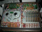
if anyone has more ideas on all this, I'll appreciate it.

... its a little sad to have her all taken apart and upside down when just earlier today she was playing the tape of my first test recordings...
but I'd like at least to take care of the AUX / EFF noise before I start in earnest. I can't really think of a work around for this (well maybe use the monitor out as an effect out?)
388 upside down.jpg
(notice the black belt is in this time!)
 
Recappin' Stuff

Hi LUNE, no problem...

I totally know how you feel, having a mostly-working machine (with a couple issues) and then taking it all apart to fix an issue. You kinda feel like your going backwards for a while. :) Don't worry though, we've all been there and the disassembly is reversible. Just a part of the process of fixin this stuff...

So, let's focus on issue 2 first. It seems like it might be the easier of the two, since we have a general idea of where the problem is, and what is likely causing it...

Most of the time you won't really be able to tell if a cap is bad just by looking at it. They do sometimes begin to bulge (look at the top, and the bottom where the leads come out) when they get really old, but perfectly normal looking ones can be bad too. If i see a few that look suspect, or i know they are old, i almost always try and replace the whole bunch.

The sharpie marks: I've seen that too! I think it is something that was done at the factory during assembly or QA. It probably doesn't have any significance for what we should be replacing. My mixer was the same though, red and black sharpie marks here and there.

One year ago i was a recapping virgin as well. It only takes a little bit of practice to get comfortable. And there are some tools that will help make things easier. Here's a quick photo of the tools you'll want to have:

recappin_tools.jpg


I started out with a cheap soldering iron from radio shack. It worked fine for a while to learn on, but there were times where it seemed too hot or not hot enough, and the tips for it were kinda cheap and wore out quick. I finally broke down this winter and got the nice Weller Soldering station with the adjustable iron. It's been well worth the 90 or so bucks. Being able to adjust the temperature of the tip is great and helps you avoid burning the traces. The replacable tips are nice too, they come in different sizes and shapes and generally last longer than the cheap ones. The other stuff in the photo... Solder sucker pump(s), tiny wire snips, long skinny forceps/pliers, rosin-core solder, a tub of rosin flux, rubbing alcohol, q-tips and a plastic poker thingy.

Once you have the supplies, find a old junk PCB that has a bunch of stuff on it, maybe something out of an old junked VCR and practice desoldering and re-soldering the caps on it. It will help ya get the feel without risking your 388. Focus on getting the caps off nice and clean without getting the PCB too hot. On some PCB's the traces will peel up if you get them too hot or burn them. Clean the empty traces and holes with the q-tips and rubbing alcohol.

Next, take inventory of all the capacitors you'll need to recap the PCB. Make a list of each cap's value (XX uF/ XX V) and how many of each. The ones in your photo are the "radial" type, where both leads come out of the same end. "Axial" capacitors will have one lead out of each end. You can get a good initial capacitor count by just looking in the manual at the parts list, but i'd take inventory of what's actually on the PCB too, just to be sure there's no discrepancies. Also look in the manual for any special notes about the capacitors. If a certain cap says B.P. it's a bi-polar cap (meaning that the leads can go in either way, no + and - side).

Once, you have your list, you'll need to pick out and order the caps. I find myself using Mouser the most, but sometimes i get caps from DigiKey and other places too. It mostly depends on where i find what i need. Once your caps arrive in the mail, you'll be ready to go.

I wish there was an easier way to test caps too. At the very least you'd have to desolder one lead just to test them with a capacitance meter. And, it's probably easier to remove the whole cap/both leads, really. Even if the cap tests fine, it's still old, so you might as well replace it with a new one, since it's out. :) I kinda look at it the same way with the whole PCB, you've taken the time to unplug everything and remove it from the machine, so you might as well refresh all the caps on it before you put it back in.

Go slow, take it one cap at a time. Take one out, make note of it's value and polarity, make sure you replace it with the same value and polarity. Then do the next... It gets quicker as you go. :)

-Tom.
 
Success!

...for issue #2 anyway - no more muffled frying oil!
and I'm no longer a virgin!:)

it all went pretty smooth, i only recapped the electriolytics on the monitor pcb as i figured this must be where the noise was coming from (earlier in the post I had some faulty reasoning, suspecting it could have been in one of the buss pcb boards, i'm not sure why i thought that though...) I did just a couple practice desolders/resolders on some capacitors in something broken I had laying around then just went for it. the variable temp solder station i got is much nicer to use than the cheap solder gun i had before. i could imagine getting more skilled in this in the future (it took me about 2 hours for 21 capacitors) but i'm just pleased at the moment that i didn't fry anything...

so i'll study up another time to try to figure out the channel 5 VU problem (issue #1) but for now i'm going to rest on my laurels with the recapping triumph and start using the machine to do what it does... i can work around the VU problem.
 
Back
Top