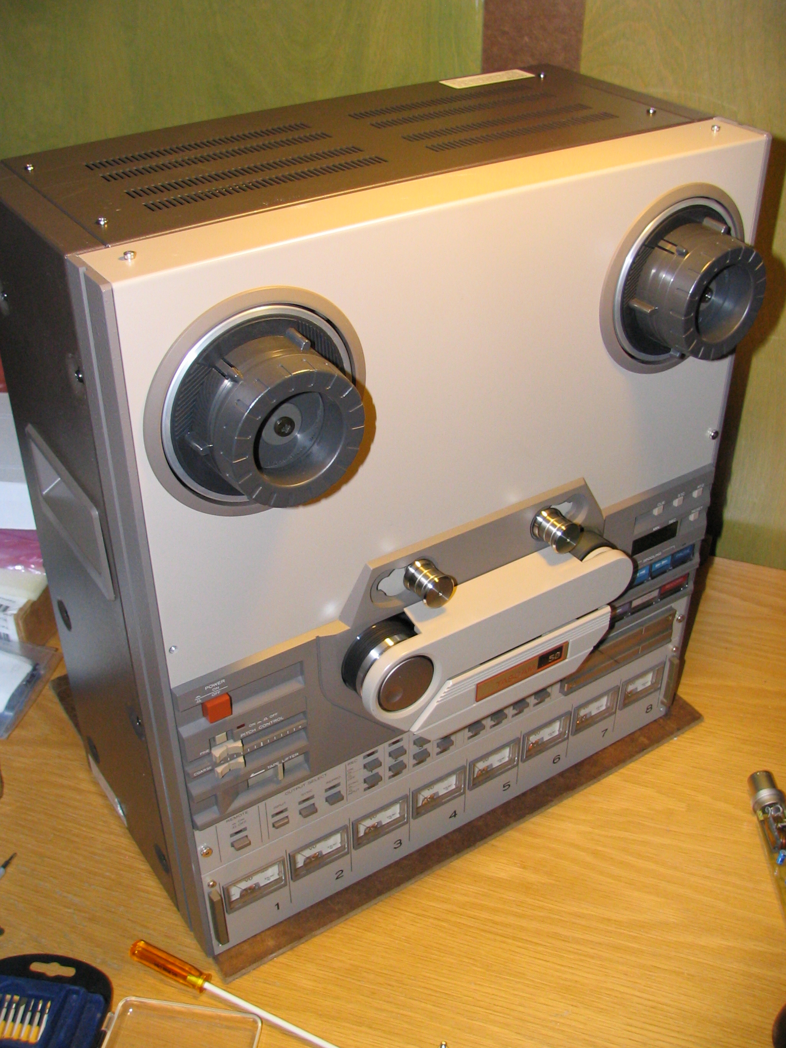
Tascam 58-OB Story...

Did some load testing...

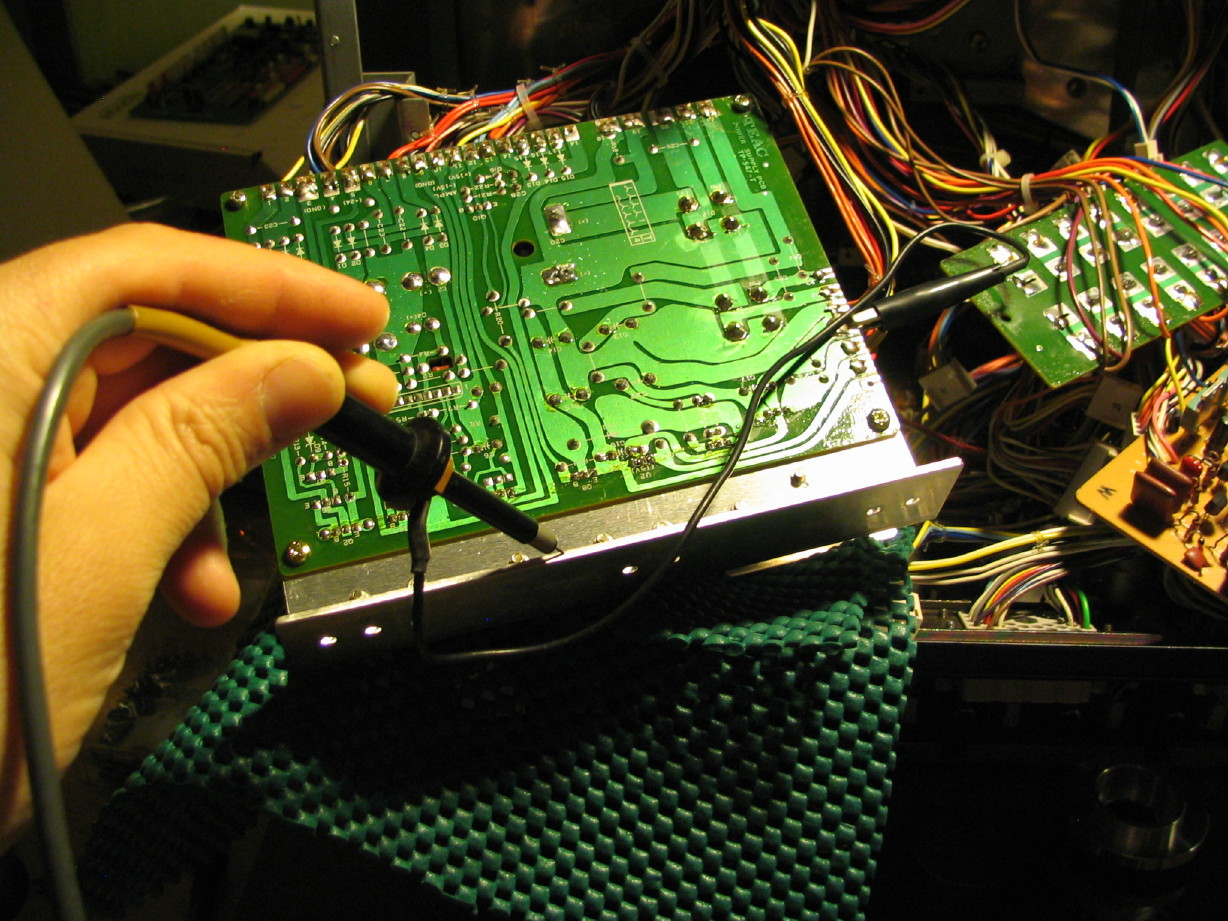
I followed Ethan's advice and wired two light bulbs together in series to load test the 24V rails that come to the Capstan Servo PCB. The bulbs used were an auto industry bulb, trade # 1141 which is a 12.8V 1.44A bulb. So if I'm correct, the two bulbs wired in series creates a 25.6V array, and the PSU ideally sees a 2.88A load. Is that right?

So here are the results...

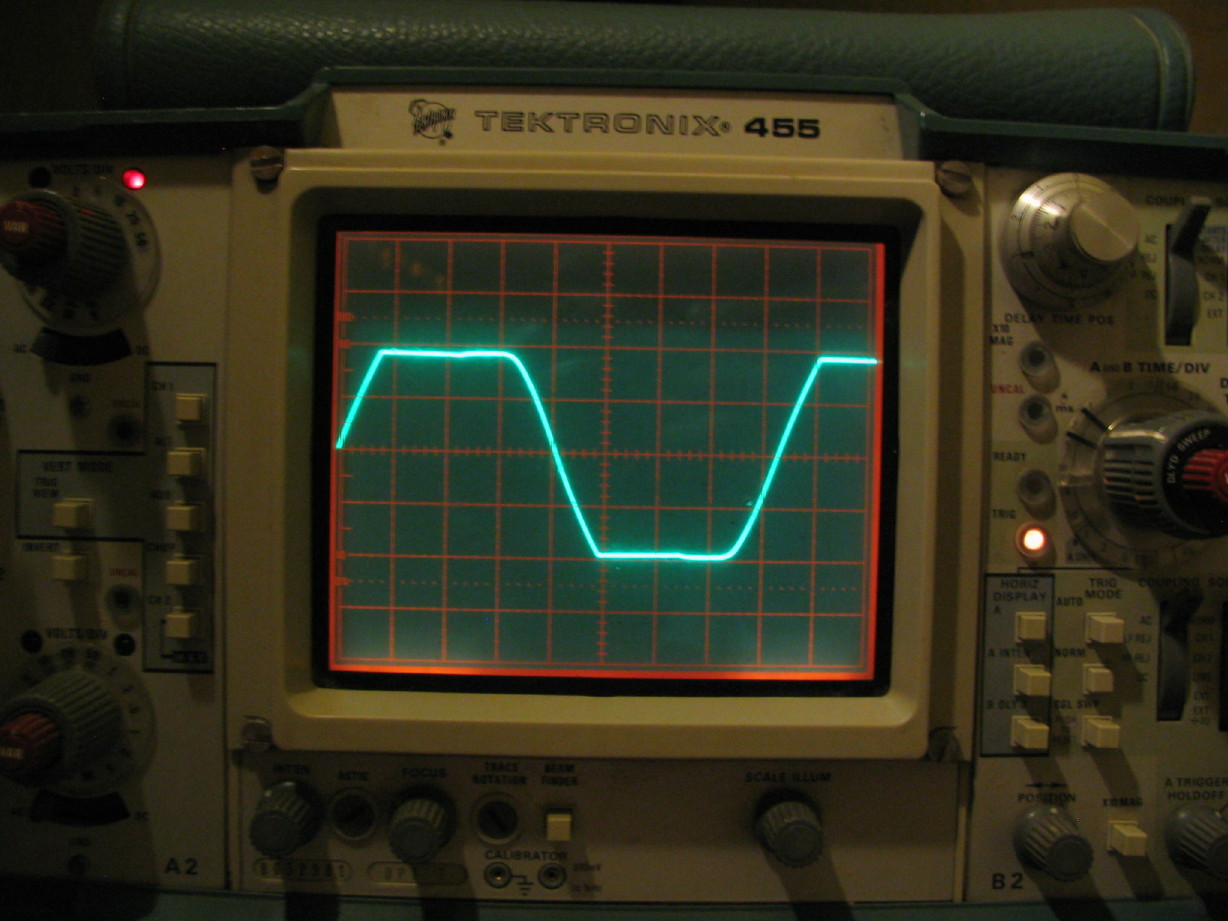
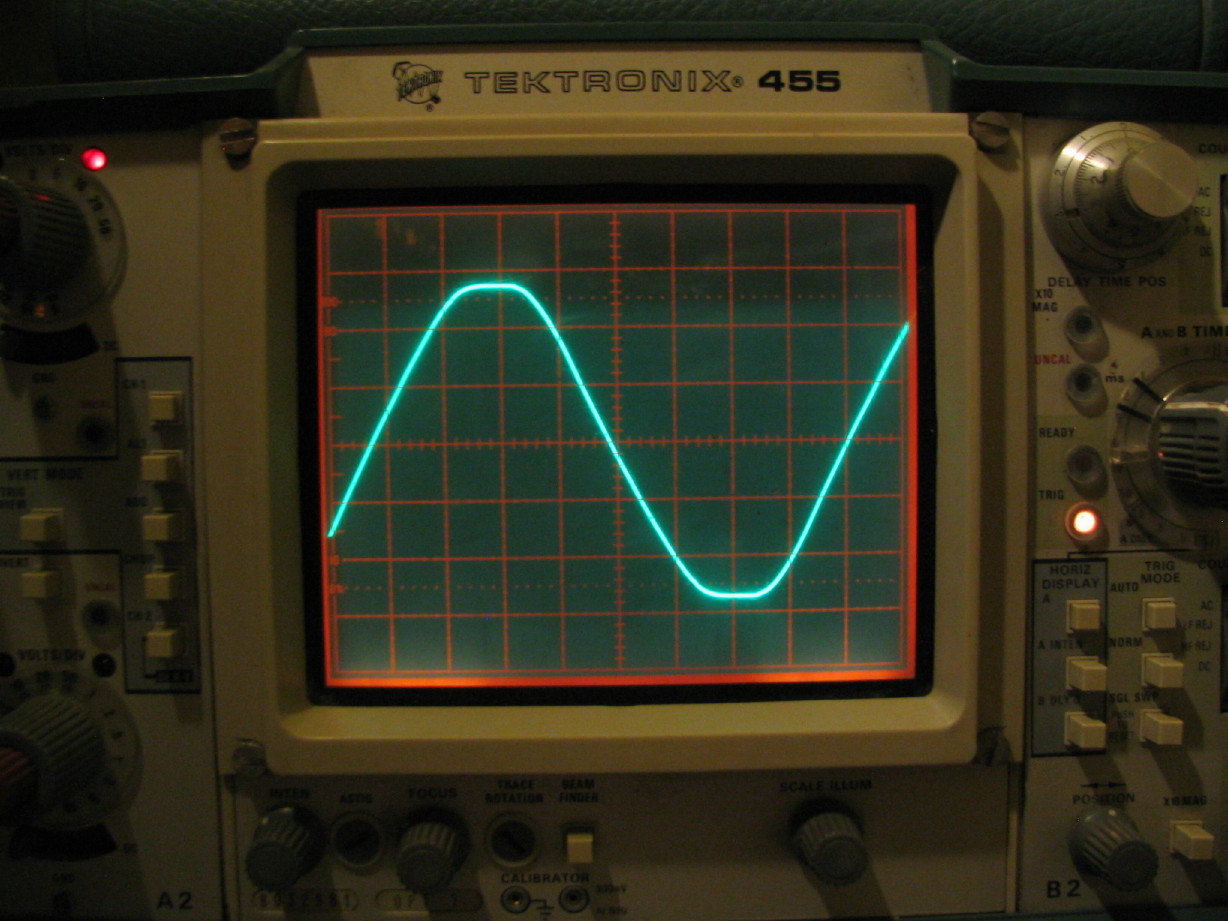
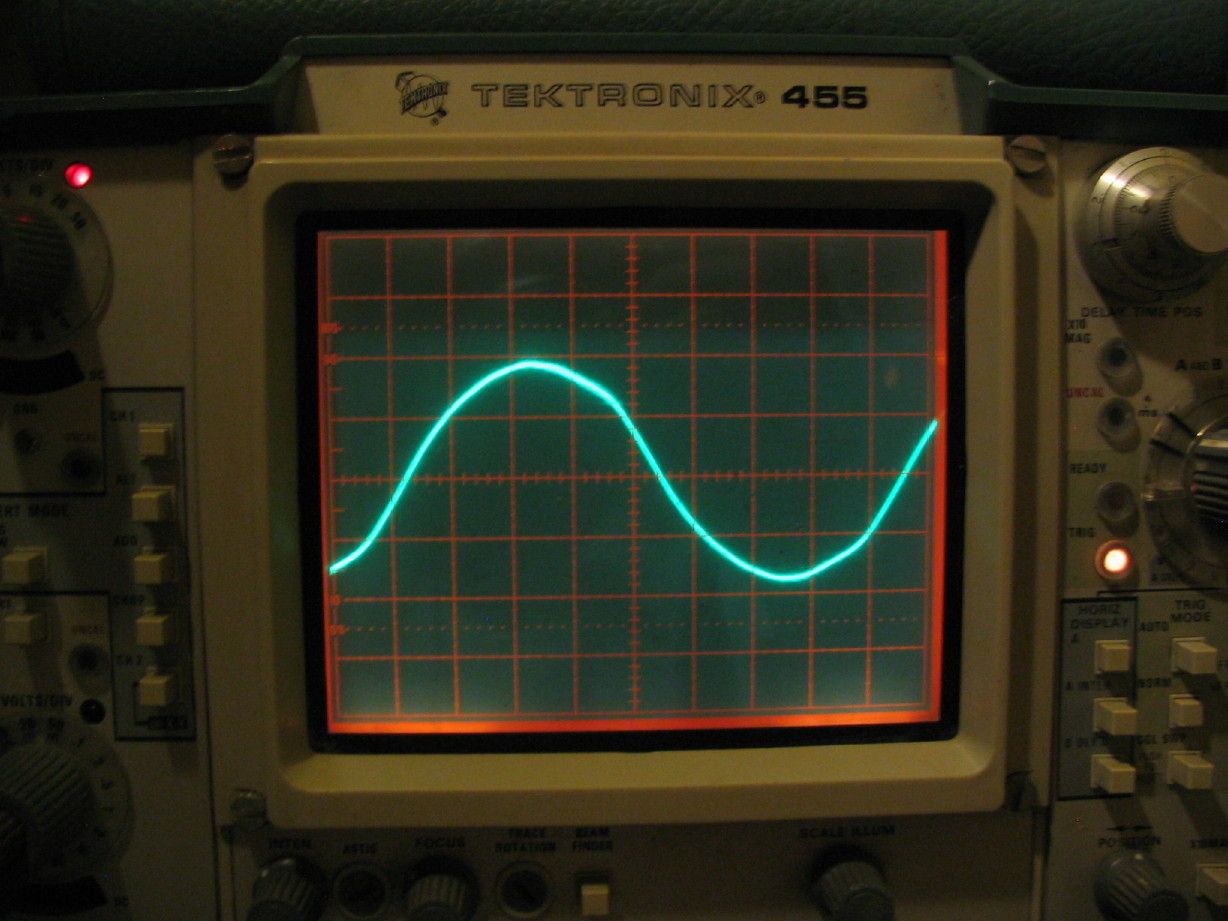
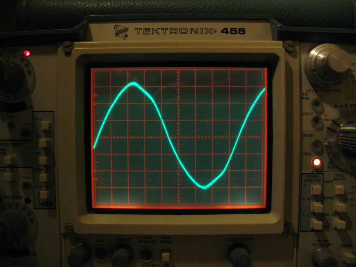
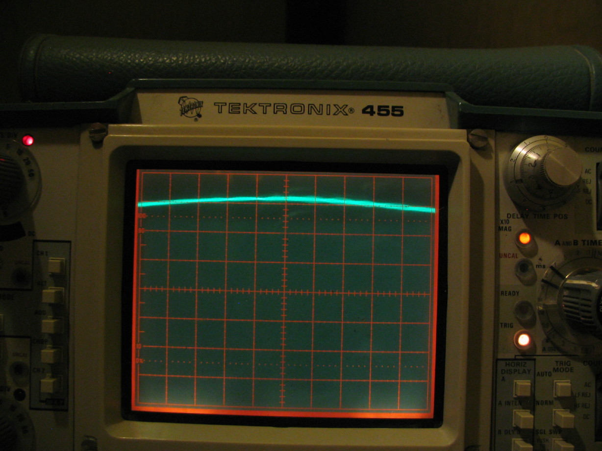
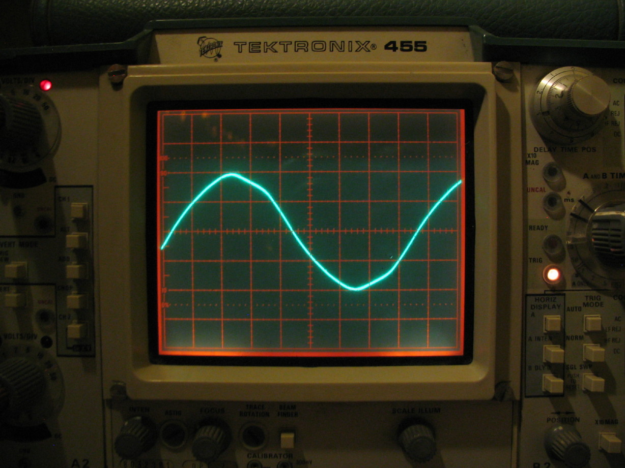
Here is the pre-load voltage on the regulated 24V rail:
IMG_2123_1_1.JPG


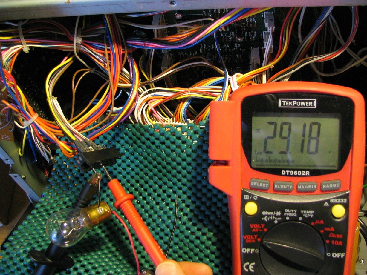
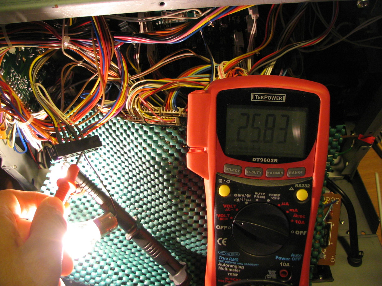
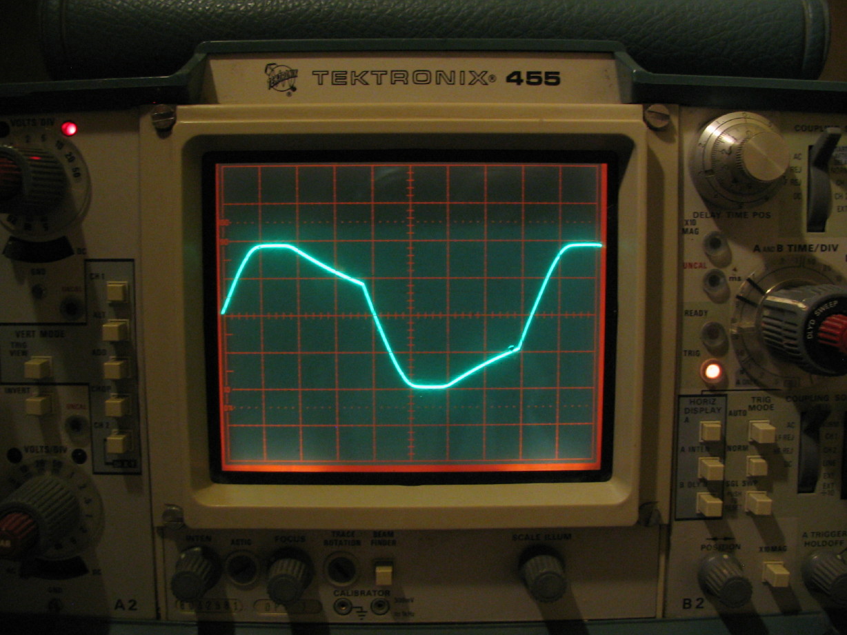
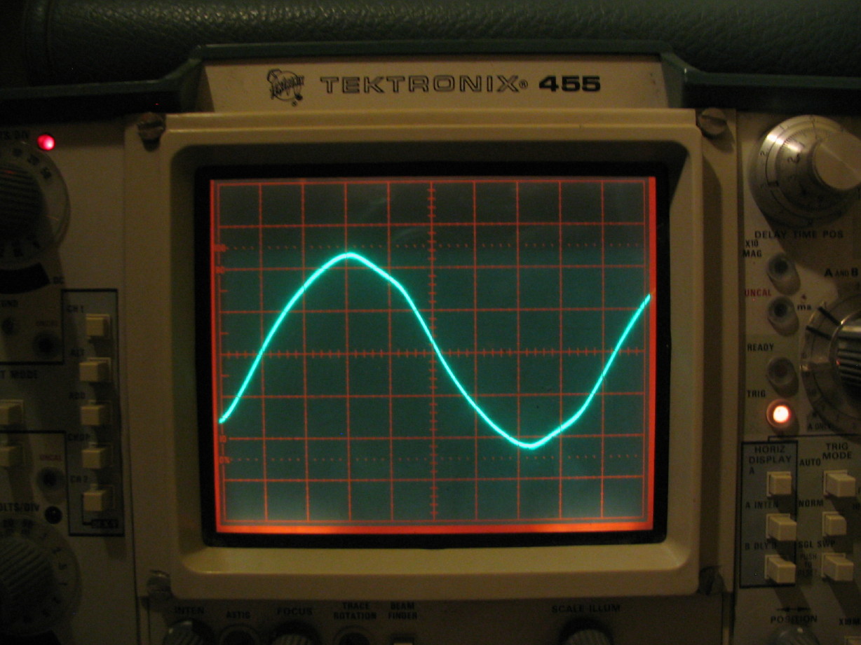
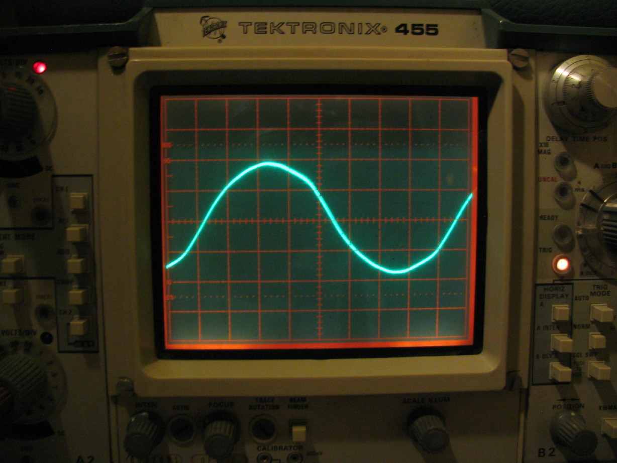
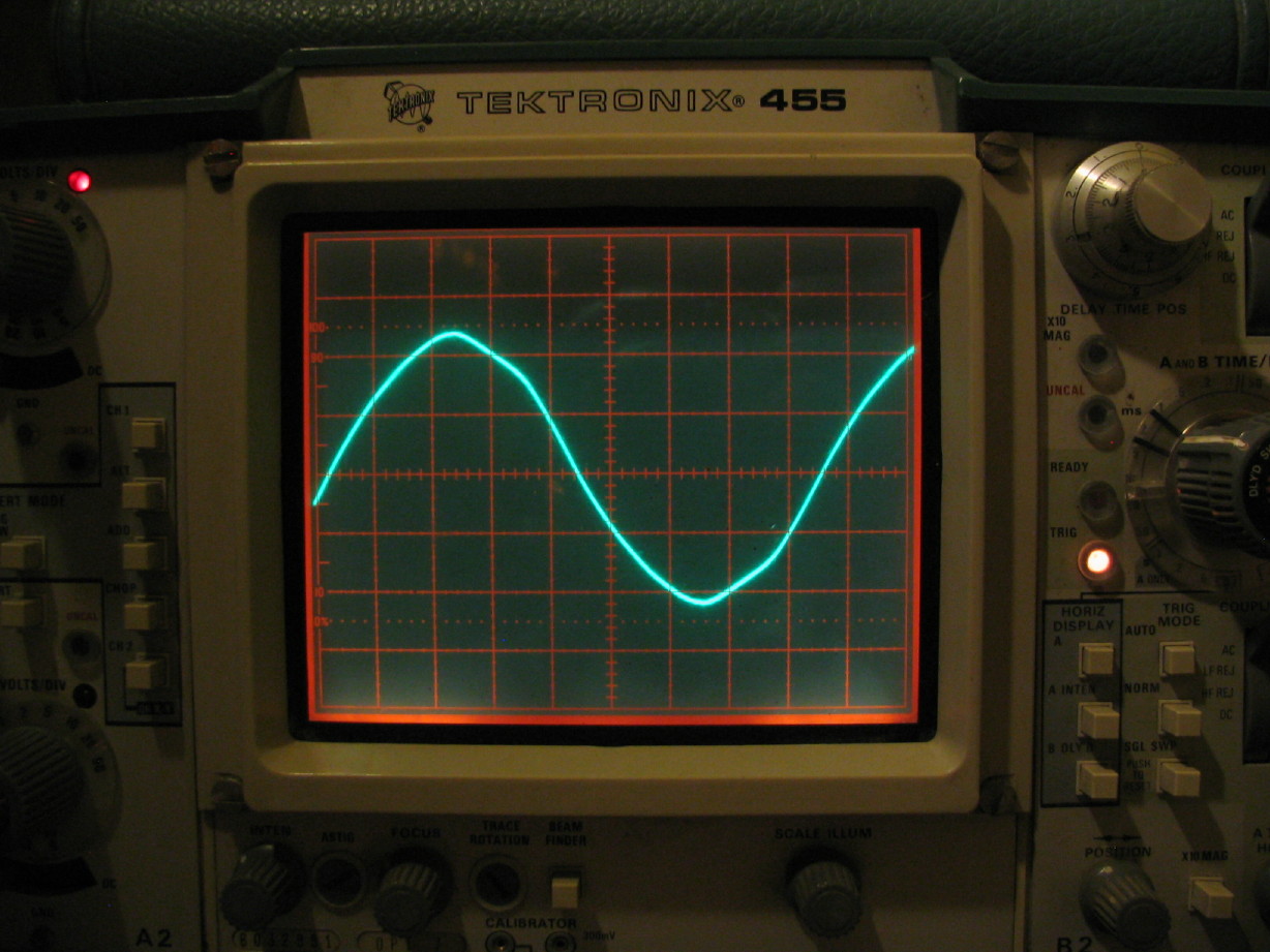
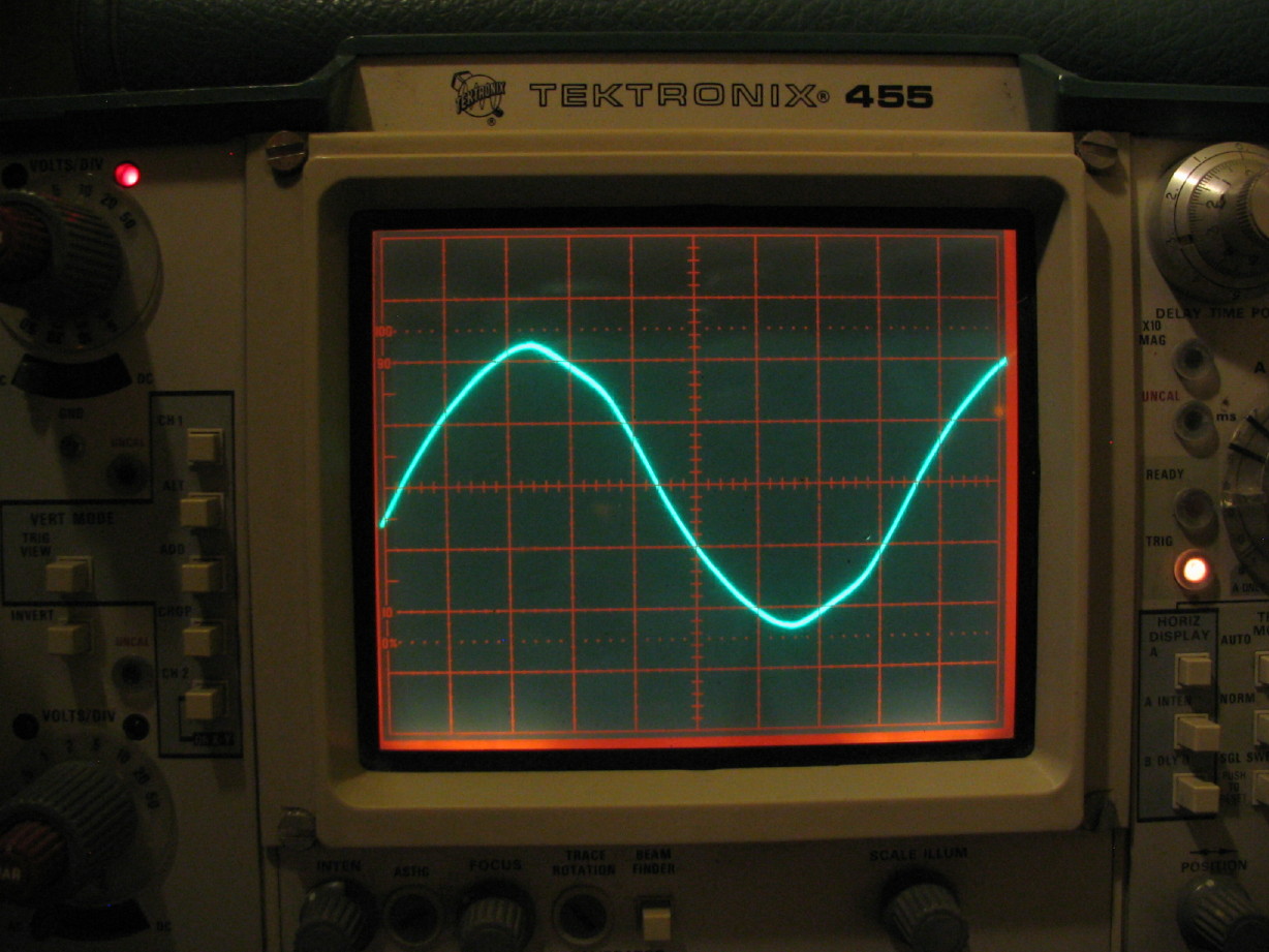
Here is the voltage while under load (and the bulbs were burning about that bright and lit instantly when the 58 was powered up):
IMG_2124_2_1.JPG


So we lost not quite 3V on a nearly 3A load.

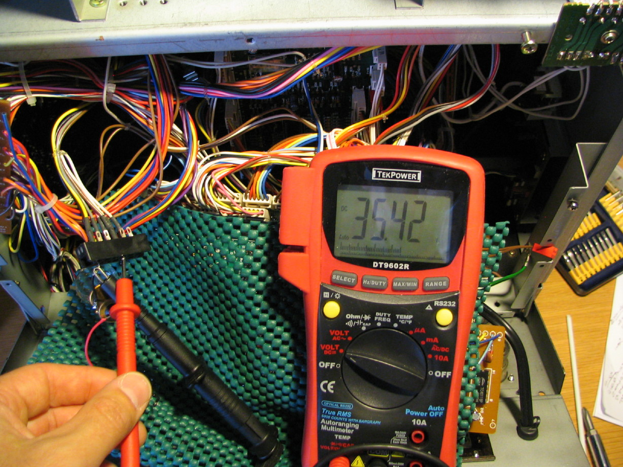
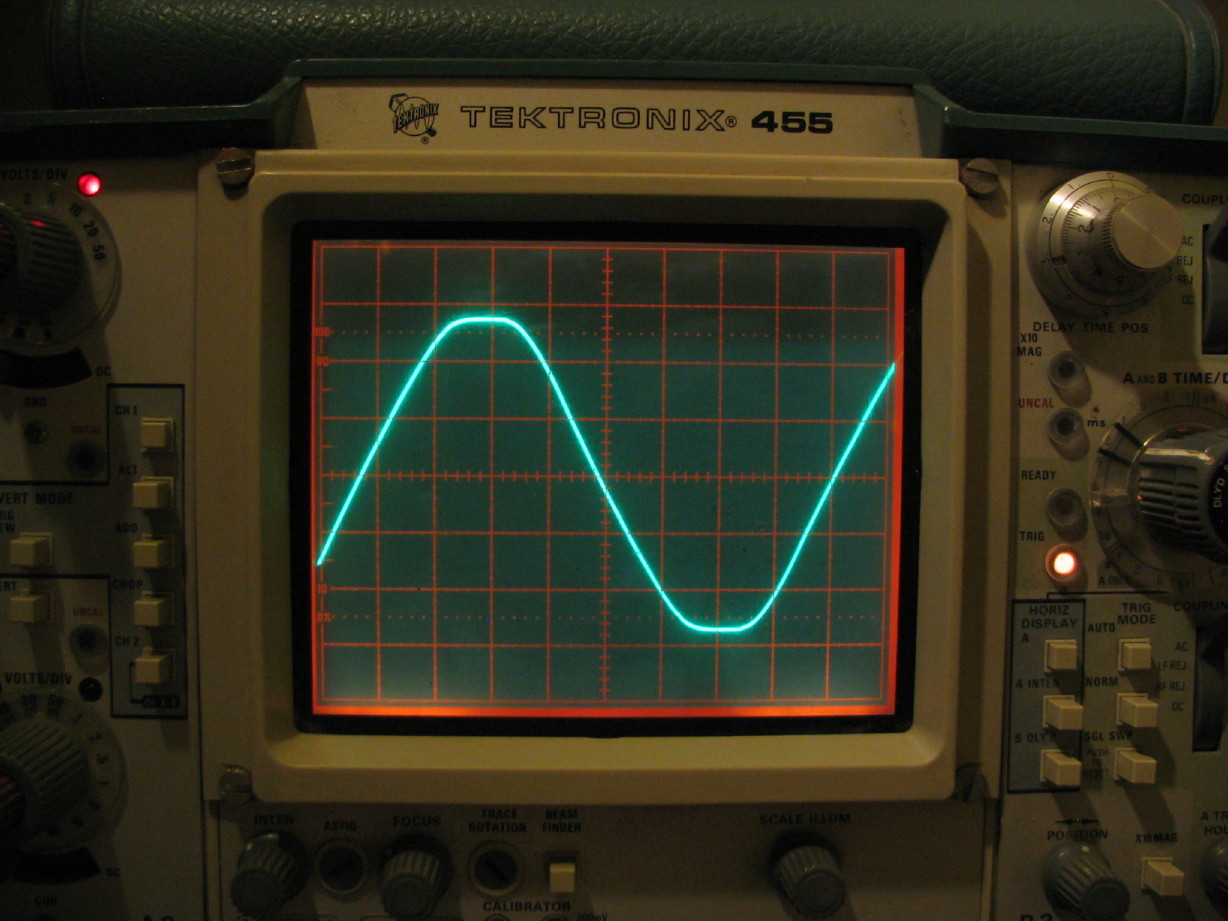
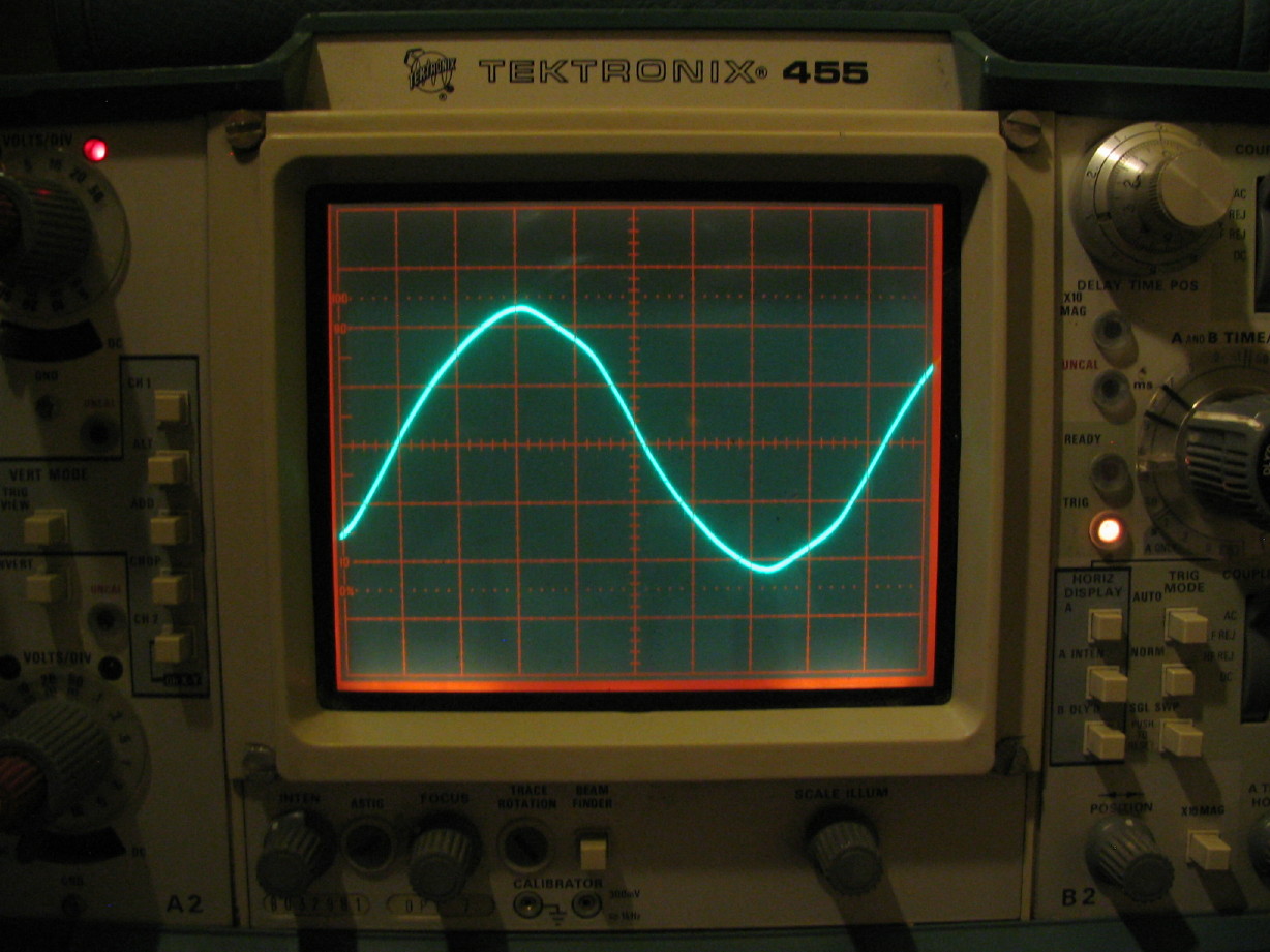
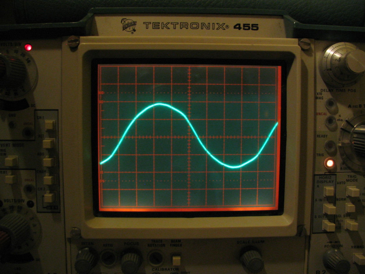
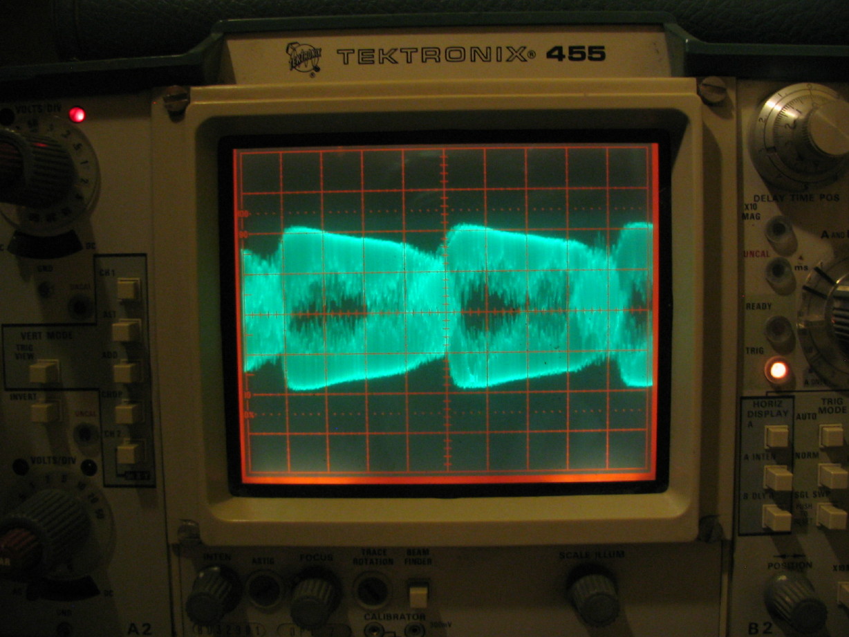
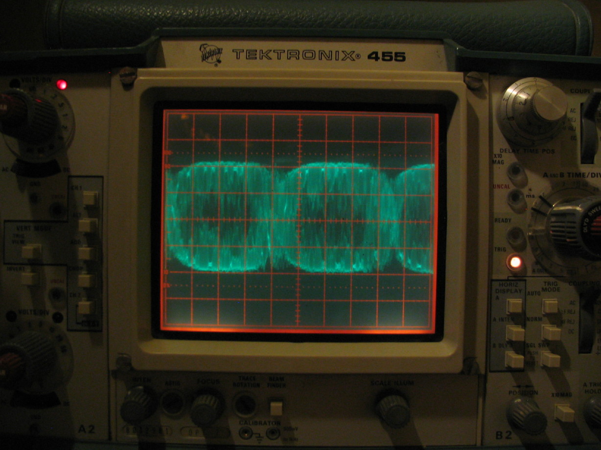
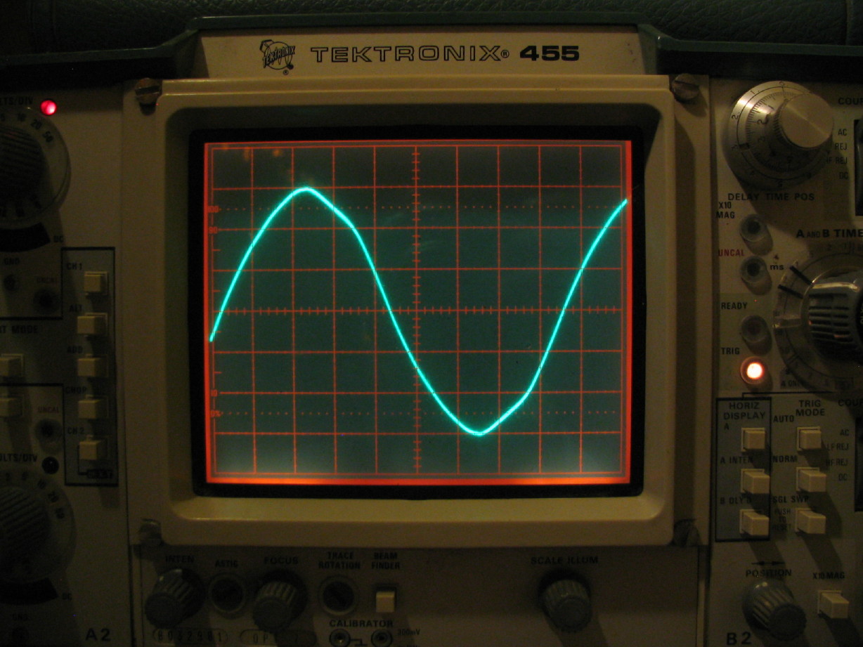
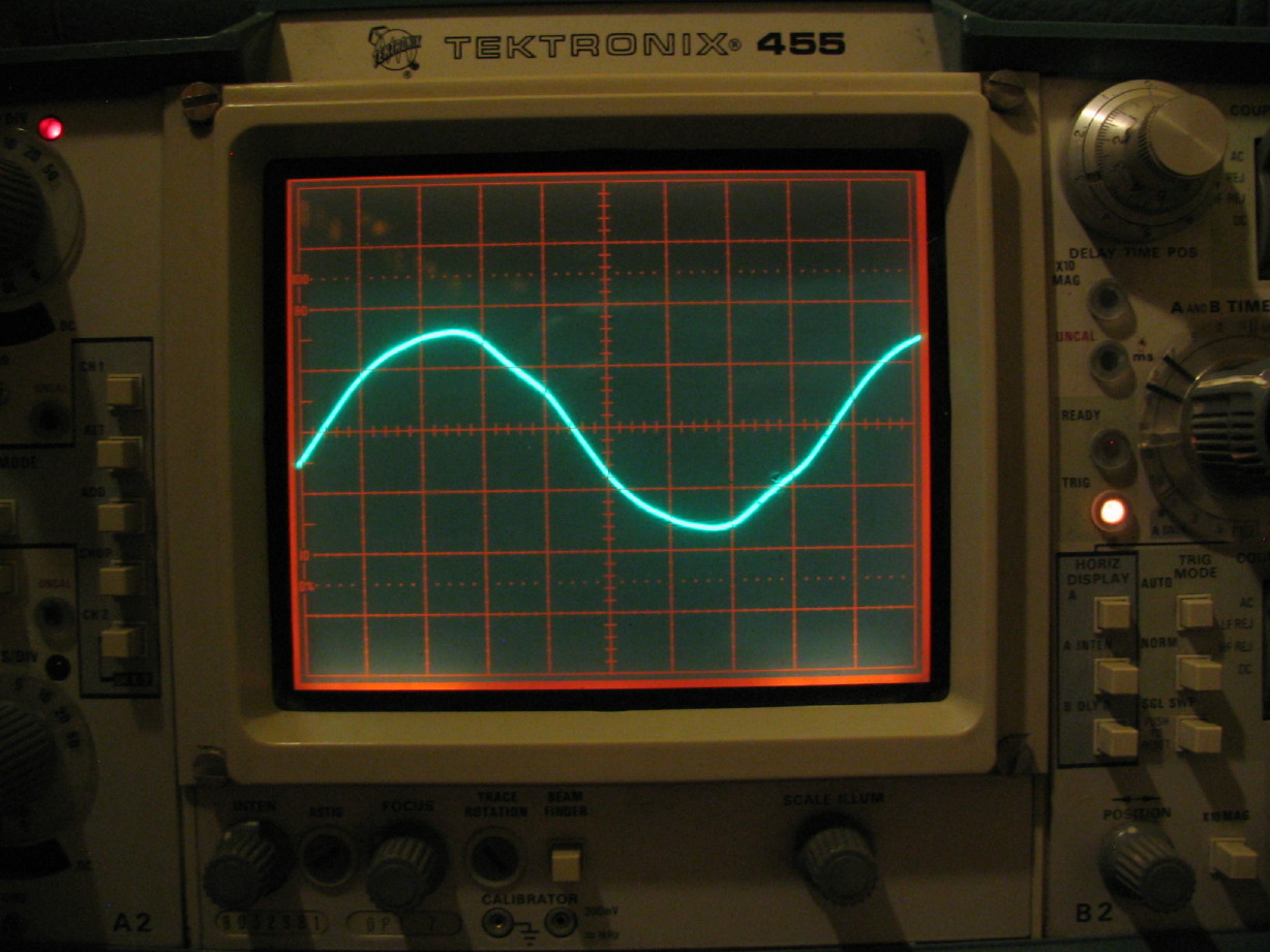
Now, on the unregulated 24V supply, here is the pre-load voltage:
IMG_2125_3_1.JPG


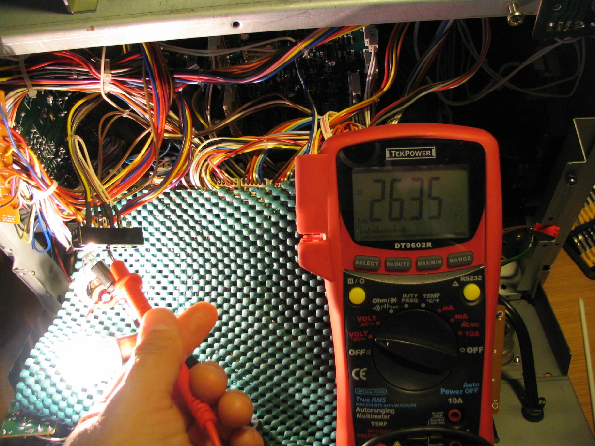
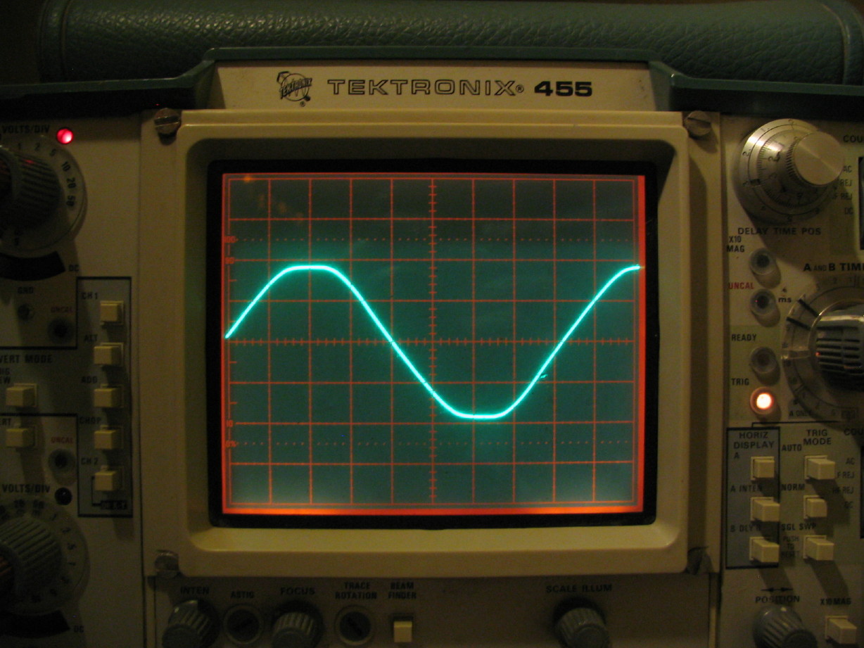
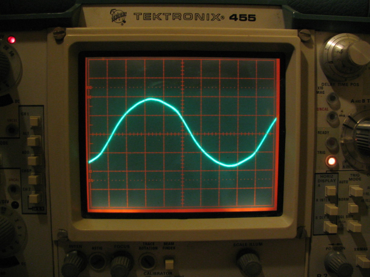
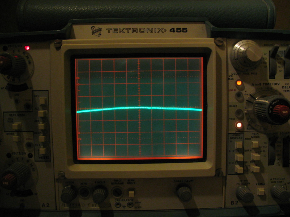
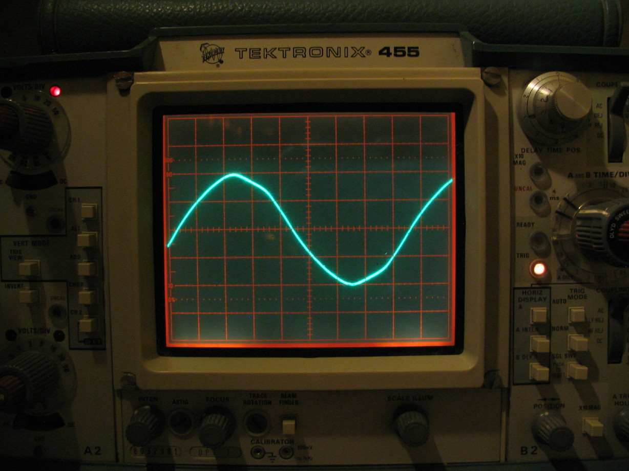
And here is the voltage while under load:
IMG_2127_4_1.JPG


That seems like a lot of voltage drop (about 9.5V), but I don't have a good sense about what is reasonable for the supply under that kind of load...also, maybe means nothing, but the lamps lit gradually when the 58 was powered up...may mean a problem :confused:, or maybe just a cap charging...haven't looked closely at the circuit for the unregulated supply very closely.

Comments? Suggestions?
 
Voltage add current stays the same.

The voltage will add (12 + 12 = 24) but the current is a max. So it stays the same. 1.xx amps though both bulbs.

Now you know that you have a good PSU.


I'm looking at the schematics and will get some more time this weekend. Given teh "smartness" of the uP controlled seefrve you will beed to connect most of the boards together to have a good speed test.

--Ethan

PS the capstan motor is a 3 phase motor....
 
Very cool...Thank you.

Not a problem connecting the boards together as they are already mostly in and connected...I only removed supply lines from the Interface and Control PCB's...oh and the Mother PCB and the secondary supply for the blanace amp board. Take 60 seconds to hook those back up. I can probably leave the Mother PCB and the balance amp supply disconnected, yes? The Mother PCB doesn't handle any transport power, just audio and of course same with the balance amp...

I'll see if I can find a way to get those hooked back up AND have access to servo board.

3-phase...huh! But there are so many wires that go to it from the servo board... :confused:

And how come the traces look the same for the 5V, regulated and unregulated power rails? Since the vertical reads voltage per division on the scope I thought increased voltage would result in increased amplitude...:confused:
 
more smoke

So I did what any reasonably dangerous person would do and I pulled the Capstan Servo PCB and capstan motor out of my parts 58. I wanted to see if that system behaved the same as the original one in the transport (i.e. capstan motor spinning slow and weak).

It does.

In the process I started hearing the transformer humming, and that's a big transformer to hum.

I could smell that bad and unfortunately familiar smell of hot electrical, and as sick as it may sound I let it keep going since I have the parts deck and my intention was to be able to char whatever component enough so that hopefully there would be strong clues as to the nature of the root problem. I'm really okay if anybody wants to call me stupid for exercising that logic.

I thought I saw smoke coming from the little secondary power supply that powers the balance amp. Disconnected power from that and the humming stopped. Removed that power supply but could see no damage and it didn't smell bad. Inspected other PCB's and everything looked fine. Turned it back on and there was the humming and you could (after a bit) hear a sound a little like a faint version of a fried egg, uh, frying. STILL couldn't see where it was coming from...I thought this whole time that the capstan servo PCB and motor were disconnected from the system because it wasn't spinning at all. Well, so much for that assumption. It was connected and it turns out that it was a transistor on the servo PCB that was cooking...Q4. The egg sound was the small plastic insulating washer that goes on the mounting screw. The washer is now one with the transistor.

So I have to assume that the problem is NOT with the servo PCB or motor because it behaved incorrectly with the other set plugged in.

I checked the voltages coming off the power supply and they are the same as they were before so its not like a regulator is tanking...although maybe one has already tanked?

Again, here is the schematic for the Capstan Servo PCB:

https://www.torridheatstudios.com/ftp/share/documentation/Tascam/Tascam%2058/Tascam%2058%20Capstan%20Servo%20PCB.pdf

Q4 is unlabeled on the schematic but it is the transistor just to the right and below Q3 with R24 feeding the base. Yes, there are two R24's on the schematic. The R24 that limits current to pin 9 of IC1 is really R25. On the PCB the solder was melted off the leg of Q4 that goes to K1 and C33.

Tired. Headache. Going to bed.

Good news is all the transport functions still work fine.

No, Ethan, I still don't want to trade for your 38. Sorry. :o
 
Cory, mind you that I know little about this but it may be good news that it may only be a transistor that's at work here. It may be the cause of all the problems. I mean, that's what you're saying, right? Am I reading this correct?:confused:
 
Unfortunately no.

The servo pcb and capstan motor set original to my 58 and the set from the parts 58 both behaved in the same ill manner so it is safe to assume the problem is external to those two components...plus who knows if I have damaged the spare set with my entertaining hammer mechanic strategy.

FURTHERMORE, I think there are some wires coming from the arming panel that got hot enough to distort the insulation, so the problem is big at this point.

Had a face-to-face with Ethan today and per his advice I'm going to revisit scoping the PS rails now that I am armed with better knowledge about how to operate my scope (also thanks to Ethan), and I also have a reliable Tek probe to go with my Tek scope...the two that came with it are of questionable condition/quality.

The Story continues...
 
Glad to see you are still sticking with it! I haven't been able to even LOOK at my analog gear for some time, been a hell of a year it has.

Oh and fried eggs sound COULD be a transistor going.
 
Still plugging away at this even though it seems I am drifting further and further away from getting the 58 ship-shape.

This post is mostly related to some discussion evm1024 and I have had about the 58 and the capstan motor and Servo PCB outside of the forum, but I thought this would be of general interest...I dismantled a 58 capstan motor to have a look inside.

First off, the Servo PCB schematic shows three variable resistors on the upper right of the schematic. Ethan was wondering what these were labeled since they aren't labeled on the schematic...well, it looks as though there are only two trimmers installed (with space for the third), and they are labeled H and L and M...trimmers are installed at H and M:

IMG_2239_9_1_1.JPG


Now, on to the motor.

There is an element on the schematic labeled "FG". We figured that was some sort of speed sensor. Well here's the thingy to which I think FG refers (the silver thingy):

IMG_2230_1_1_1.JPG


When I remove it it looks like this:

IMG_2231_2_1_1.JPG


IMG_2232_3_1_1.JPG


It looks like a tape head doesn't it?? Maybe a magnetic sensor?? Here is a profile closup of the toothed disk that the sensor is mounted close to:

IMG_2240_10_1_1.JPG


Okay. So now for the other black thingy mounted on the side. Ethan had names for all these things and now I can't remember but I kind of remember what they do...its a 3-phase motor but each phase has on and off so there are 6 control elements that you can see in the lower half of the schematic (BTW, I've mentioned a couple times about the schematic not showing the motor or connections to the motor...Ethan pointed out to me they are actually all there. The Servo PCB and motor are all integrated into one schematic which now makes sense because the two sections are constantly interacting.) So anyway, here is the black thingy coming off and then what's on the other side and you can see the 6 control elements:

IMG_2234_5_1_1.JPG


IMG_2233_4_1_1.JPG


When I take the shell of the motor off you can see the rotor really well and there are actually 6 sections on the rotor as well...3 of the lighter sections and 3 of the darker sections...this rotor is interesting to me because I've only taken apart reel motors as far as open reel transports are concerned and this rotor is external to the windings:

IMG_2235_6_1_1.JPG


The top and bottom half of the motor easily slide apart...no pressed on bearings. I just slid the top half with the nose bushing and windings off the capstan shaft leaving behind the rotor, tail bearing and thrust bearing. BTW, this confirms that this capstan motor was ideally designed to be in a tilted or horizontal position. The nose bushing is a bronze type, the tail bearing is an easily sourced 608Z type cartridge bearing which coincidentally is the same type used thorughout the 58 with the exception of the scrape flutter filter:

IMG_2237_8_1_1.JPG


IMG_2236_7_1_1.JPG


So anyway (Ethan) that doesn't tell us much, but it does visually tie together what we are seeing on the schematic yes?

Now here's where things get ugly...it does appear that a number of wires that carry that unregulated 24V supply were getting heated when I had it powered last week resulting in distorted jacketing. That unregulated supply rail goes to the Mother PCB (to which the amp cards connect...that's where the original mishap occurred and I replaced that one cooked resistor, but there must be more that was damaged??), and there are also wires with distorted jacketing that go between the Function A PCB and the Control PCB. So you see, all these areas are in qustion, and I'm not sure if the PSU is pushing too much voltage or if something is drawing too much current.

I'm going to go back to square 1, pull the PSU and scope each power rail and put up the results.

Here is a sample shot of wiring with distorted jacketing:

IMG_2242_12_1_1.JPG


So sad...
 
The "head" is a head and the teeth together make up a tachometer. The head sends a pulse for each tooth and allow precise speed control.

THe motor is quite advanced. It uses the tach for motor speed control, Modulates the rotor and stator coils timing for both speed control and torque control. Other motors (the 32,34,38 for example) only change the current to the motor achieve speed control. Don't adjust any pots!

This of couurse makes it quite difficult to troubleshoot.

So, Cory - this is a replace or repair job. Don't go too deep. Wires that are not exposing the conductor are still good. And they are good indicators of where to look for the next problem. There are some blown semiconductors still out there and who knows what. Keep looking.

-Ethan
 
for some reason seeing the capstan motor dismantled like that made me cringe :eek:

But anyway, as EVM says, this is the same basic idea as the Revox B77 capstan design.

They use the toothed wheel and a hall-effect sensor to generate a waveform ('FG' is most likely Frequency Generator) which is compared against an onboard oscillator, and that is used to generate a suitable frequency to drive the capstan motor. IIRC it's an 800hz clock on the Revox - the TASCAM is likely slightly different but it seems to use the same basic principle.
 
Thanks guys.

Ethan and jpmorris, thanks. That makes perfect sense. Nifty little device that toothed wheel and head.

That is encouraging to know that as long as the jacket is intact the wiring is still good.

Sorry to make you cringe, jp. :o It actually was very easy to access and would be an easy motor to refresh bearing-wise. I'm being quite careful to handle everything appropriately...and that IS the spare motor BTW. :)

All my most regretted mishaps have come when I have been rushing or trying to push too much through in too little time. I'm slowly learning. It is better to savor the experience and let safety dictate the pace. Might seem obvious to do it that way, but I tend to be goal-oriented...I get an idea of what I want to get done and then try to fit that within the time limitation rather than accomplish whatever can safely be accomlished in that time limit.

I scoped every input and output point on the PSU PCB last night and took pics of the scope screen for every one for which I could get a trigger. I'm putting that all up in the next post. It will be a long one. Hope to get comments and I promise to be patient because I know it will take a bit of time to go through.
 
Power Supply PCB Scope Pics...

There are 28 input and output connections altogether on the main PSU PCB in the 58. Basically what I did is just went right down the line from Pin 1 to Pin 28 and got a picture of the scope screen for each where able. The scope TIME/DIV setting was always 2ms/DIV. I'll specify for each what the VOLTS/DIV setting was. Where I have specific concerns/questions I've made the text color RED. Also, the scope channel used was always set to "AC coupled".

First off, I'm really concerned that either I don't know how to read my scope right, or my scope is wonky...I'll point out specific examples below but, for instance, the waveform will be 18 volts on something that my digital multimeter (DMM) will be reading as 5 volts. More below.


Pin 1: This is an input from the main transformer that ultimately powers a +24VDC rail. I thought this was the unregulated 24 volt supply but all the components in the chain between input and output look to me like regulated...? And that waveform looks wierd...almost half square and half sine... VOLTS/DIV was set to 10V.

IMG_2269_1_1.JPG


Pin 2: This is an input from the main transformer, the other leg of Pin 1, same scope settings...That waveform also looks odd...

IMG_2270_2_1.JPG


Pin 3: This is an input from the main transformer that connects to ground.


Pin 4: This is an input from the main transformer that directly powers the 6VAC rail for VU lamps and such. VOLTS/DIV was set to 5V. If I'm reading the scope right that is about an 18 volt differential?? :confused:

IMG_2271_3_1.JPG


Pin 5: This is the output of the above mentioned +24VDC rail powered by the transformer via pins 1 & 2. I get about +35VDC on my DMM when measuring between Pins 3 & 5, but I cannot get a trigger on the scope...


Pin 6: This is a ground.


Pin 7: This is an input from the main transformer that powers the +/-15VDC rails. VOLTS/DIV set to 10V.

IMG_2272_4_1.JPG


Pin 8: This is an input from the main transformer. This is the other leg of the input on Pin 7. Scope settings the same as with Pin 7.

IMG_2273_5_1.JPG


Pin 9: This is a ground.


Pin 10: As with Pin 5 I get a reading on my DMM but cannot trigger the scope. The DMM reads about -15VDC when measuring between Pins 9 & 10, but I can't trigger it...


Pin 11: Same issue as Pin 10...DMM reads approximately +15VDC but can't trigger it...


Pin 12: Pins 12 ~ 17 deal with the solenoids and I think the lifter mute circuit. Not gonna chase that down right now but the VOLTS/DIV was set for 20V for this one, as well as Pins 13, 14, 15, 16, and 17.

IMG_2274_6_1.JPG


Pin 13:

IMG_2275_7_1.JPG


Pin 14:

IMG_2276_8_1.JPG


Pin 15:

IMG_2277_9_1.JPG


Pin 16:

IMG_2278_10_1.JPG


Pin 17:

IMG_2279_11_1.JPG


I noticed that the waveforms looked a little more rippley than others for all of Pins 12 ~ 17 so I used the x10 magnification feature to zoom in on a waveform apex to have a closer look...Looks okay?

IMG_2280_12_1.JPG


Pin 18: This is a ground.


Pin 19: This is the output of the other 24 volt supply rail...whether it is regulated or unregulated depends on the answer to my question under Pin 5...anyway, no reading on the DMM, and nothing to trigger with the scope. This rail is dead.


Pin 20: This is an input from the main transformer that powers the 24 volt rail that is dead. Couldn't see much at 10V/DIV but there was something so I zoomed in to 0.2V/DIV and saw this...looks cool and wierd:

IMG_2281_13_1.JPG


Pin 21: This is an input from the main transformer; the other leg of Pin 20 and it looks equally wierd. Might have something to do with why the 24 volt rail on pin 19 is dead? Hm...I should've checked the fuse...VOLTS/DIV is still set to 0.2V/DIV here...

IMG_2282_14_1.JPG


Pin 22: This is an input from the main transformer. It finds its way to the +5VDC logic control voltage. VOLTS/DIV was set to 20V.

IMG_2283_15_1.JPG


Pin 23: This is an input from the main transformer that finds its way to an unused 24V supply on Pin 28, ans well as all the mechanical rails on Pin 12 ~ 17. VOLTS/DIV was set to 10V.

IMG_2284_16_1.JPG


This also looked to have more ripple so I zoomed in again using the x10MAG function and here is the apex if the waveform:

IMG_2285_17_1.JPG


Pin 24: This is an input from the main transformer, the other leg of Pin 23. VOLTS/DIV was set to 20V.

IMG_2286_18_1.JPG


Pin 25: This is a ground.


Pin 26: This is the output of the logic control rail supplied by the main transformer at Pin 22. VOLTS/DIV was set to 20V. That looks like a LOT more than 5 volts if I reading the scope right...

IMG_2287_19_1.JPG


Pin 27: This is the output of a +15VDC rail that makes its way to the Control and Mother PCB's. VOLTS/DIV was set to 20V.

IMG_2288_20_1.JPG


Pin 28: This is the aforementioned unused 24 volt rail. VOLTS/DIV was also set to 20V here...

IMG_2289_21_1.JPG


Now, just for fun, I was curious to see if there was anything going on with the bracket that a bunch of the regulators attach to. it doubles as a mounting bracket for the PSU PCB as well as a heat dissipation path. Well, I put the ground lead of the scope probe on Pin 25 for ground reference, and touched the probe to the bracket like this:

IMG_2291_23_1.JPG


This is what I got...:eek:...VOLTS/DIV was set to 20V. I measured with my DMM and only got millivolts but it kept climbing and climbing over time. I got impatient and stopped checking when it got to about 1 volt. There should be NOTHING there right? There are little dielectric pads between the regulators and the bracket as well as dielectric shoulder washers between the transistors and the mounting screws. I measured for continuity between each transistor and the bracket and there was nothing there for each, and I can see no other place where current could get through to/from the bracket...:eek::eek::eek:

IMG_2290_22_1.JPG


I will patiently await any responses. I know this is a lot, but I think this gives a really good foundational starting point to get this thing figured out.
 
ah huh

Pins 1 to 2 are self referencing (don't use the system ground). in general all power transformer windings should be measured with a DVM on AC. No meaningful to measure referenced to system grouund.

Pin 4 - You are seeing 18 volts peak to peak. first 9 volts peak flows positive then it reverses and flows 9 volts negative. THe reference is the 0 volt point. 9 volts peak times 0.707 gives 6.3 VAC RMS. Your DVM in AV should read about 6 volts across pins 3 and 4

Pin 5 - No triggering when AC coupled means no AC voltage (no ripple if the DVM gives a DC voltage) Which is good for a +24 volt requlated rail.

Pins 7 and 8 look good.

Pins 10 and 11 look good too (no ripple on DC rail, measure with DVM)

Pin 12 through 17 are the control, hold and flash voltages for the solenoids. I'm not sure that these are drawn accuractly.

Measure pin 20-21 with a DVM. They are not ground referenced.

Pin 19 should read 24 volts on a DVM with a little ripple. A blown fuse or blown bridge rectifier (D12)

Pin 22-23-24 all reference each other. voltage between 22-23 should equal voltage between 22-24. AC of course.

Pins 26-27-28 should all be DC voltages. 26 is regulated 5 volts, 27 is regulated 15 volts and 28 is unregulated 24 volts (should have some ripple)

Best guess is that D10 is blown and most likely U2 and U3. Hopefully all yout TTL IC (logic IC that take 5 volts) are not blown up too.

Of course this is just what I think might be happening......

Good luck.

--Ethan
 
Pins 1 to 2 are self referencing (don't use the system ground). in general all power transformer windings should be measured with a DVM on AC. No meaningful to measure referenced to system grouund.

Got it...I can see that now because the "ground" reference for Pin 5 is not created until after the AC current at Pins 1 & 2 (right? AC?) go through the rectifier array of D5 ~ D8...is that right?

Pin 4 - You are seeing 18 volts peak to peak. first 9 volts peak flows positive then it reverses and flows 9 volts negative. THe reference is the 0 volt point. 9 volts peak times 0.707 gives 6.3 VAC RMS. Your DVM in AV should read about 6 volts across pins 3 and 4

Okay...I kind of understand...after reading what you wrote I thought "oh right! When the AC gets converted to DC after going through a rectifier you only see the positive amplitude of the AC waveform...the "push"...then I looked at Pin 4 again and its AC stright through...no rectifier...so...6VAC RMS is really talking about 18 volts peak to peak? so 9VAC RMS might look like about 25 to 26 volts peak to peak on the scope? I get the whole RMS thing...the average amplitude in manner of speaking, yes? I get 6.74VAC RMS on the DVM. Close enough right? I just scoped it again between Pins 3 & 4 and it is really close to 19VAC peak to peak which calculates to about 6.72VAC RMS. Okay. Got it.

Pin 5 - No triggering when AC coupled means no AC voltage (no ripple if the DVM gives a DC voltage) Which is good for a +24 volt requlated rail.

OHHHHHHHkay...ha! Getting that giddy feeling again. So Pin 5 IS the regulated rail. Right. Nothing in AC...clean. I switch to DC coupled and the straight trace jumps to about 3.6DIV vertically with the VOLTS/DIV set to 20V...the trace remains straight because there is no wave...its DC! And that calculates to about 36VDC which is what I see on my DVM. So the concern here is isn't +36VDC pretty high for a regulated +24VDC rail even if it is clean? And am I right that D5 ~ 8 form a bridge rectifier, and (in a coarse sense because I don't get the intricacies of it all) Q5 ~ 7 and R12 ~ 16 manage the regulation and C12 manages regulator output filtering? That seems like a pretty fancy regulator...I suppose I could just shotgun those components or at least pull a leg of each R12 ~ 16 and test for drift?

Since the capstan servo and motor depend on that regulated voltage and there is so much balancing going on in there I would think a regulated supply rail that is running about 50% over spec could cause some trouble for sure...

Pins 10 and 11 look good too (no ripple on DC rail, measure with DVM)

Right. Yes, DVM indicates -14.68 and +14.72VDC.

Pin 12 through 17 are the control, hold and flash voltages for the solenoids. I'm not sure that these are drawn accuractly.

Not sure what you mean about drawn accurately...like something is screwy with the scope? They all reference the ground at Pin 25 right?...interesting. Tonight I'm getting an identical sine waveform (albeit a bit lumpy) on 12 ~ 17 with the scope set at 50V/DIV...about 3 DIV peak to peak in AC or DC coupled modes...:confused: That's referencing the ground at Pin 25. I tried referencing the ground at Pin 18 instead and I get no AC component for 12 and 13, about 1.2V AC ripple at 14 ~ 17; about +33VDC at Pin 12, nothing at Pin 13, and about +16VDC at all the rest...

Measure pin 20-21 with a DVM. They are not ground referenced.

Fuse F7 was blown. I now get 22.2VAC RMS between 20 and 21 with the DVM. The scope concurs and the waveform looks clean...about 61VAC peak to peak, and now when I scope between Pins 18 & 19 I get no AC component (unless I zoom in to 50mV, and even at that I can't get a stable trigger and I suspect it might be environmental noise I'm seeing anyway) and the DVM shows +29.2VDC.

Pin 22-23-24 all reference each other. voltage between 22-23 should equal voltage between 22-24. AC of course.

Yep. Got it. 22 to 23 is 12.2VAC RMS as is 22 to 24.

Pins 26-27-28 should all be DC voltages. 26 is regulated 5 volts, 27 is regulated 15 volts and 28 is unregulated 24 volts (should have some ripple)

Pin 26 to Pin 25 shows +4.9VDC with the DVM. Scope still shows a gihugic AC component as well as a sine wave when DC coupled. Same kind of story with Pin 27 too only nothing showing on the DVM. Pin 28 is still like the the others on the scope in AC or DC modes but the DVM shows +32VDC. I see what you mean...the PSU has been throwing nasty power at the IC logic. :( 
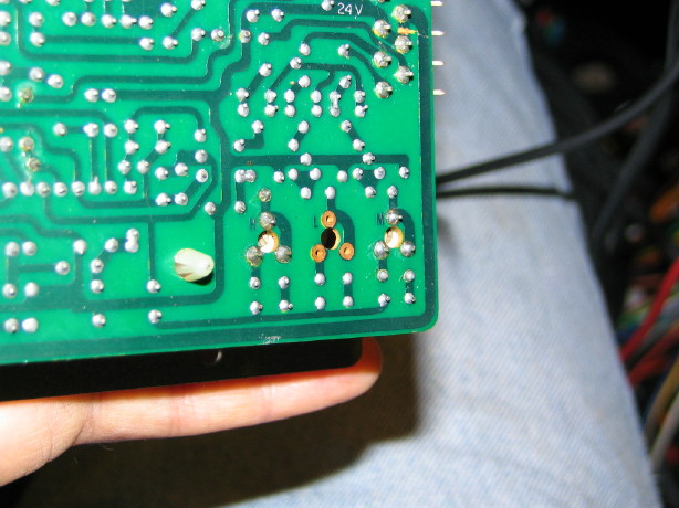
Huh...yeah. If I measure the + and - output terminals of D10 with the DVM I get 5.2VAC RMS. That's not a good bridge rectifier. I'm going to shotgun U2 and U3 even though U2 was a brand new part I just put in after the original extender card offset debacle...it ain't workin' now.

And what of the power component I'm getting at the PSU mount bracket??? I measure about 1.4VAC peak to peak ripple and I get the same waveform in DC mode too. :eek: Maybe a cooked regulator, even though I didn't get any continuity with the DVM...

SO:

  1. Get the regulated +24VDC rail at Pin 5 better regulated, yes? Can you help with that? Am I on the right track with my thoughts above?
  2. Get the regulated supplies at Pins 26, 27 and 28 working right...
  3. Try systems out again...

Thanks Ethan...you rock
 
getting it....

When pin 1 is driven positive, pin 2 is driven negative. Then diode D5 conducts and the positive pin 1 current flows to C10 + side. D7 blocks pin 1 from the - side of c10. Pin 2 is negative so D6 blocks pin 2 from passing negative current to C10 + side. And D8 conducts the negative current to C10 - side.

When pin 1 is driven negative, pin 2 is driven positive. Diode D5 then blocks keeping the negative pin 1 from the + side of C10 and D7 conducts the negative pin1 to the - side of C10. Pin 2 is positive so D6 conducts pin 2 current to the + side of C10 and D8 blocks the positive pin2 from the - side of C10.

http://hyperphysics.phy-astr.gsu.edu/Hbase/electronic/rectbr.html

They show it better than my words.

-----------

The voltage through the bridge is now available across C10. By grounding C10 - side we establish a ground reference. First pin 2 then pin 1 are grounded through their respective diodes. Alternating with the alternating current. :cool:

Q5 is the series pass transistor of the 24 volt regulator. It does the actual regulation. That you do not have 25 v at pin 5 (with pin3 your ground reference) tells me that your regulator is blown... (shorted) or the regulation drive circuit is blown.

D9 is a 6 volt zener diode. (EQA01-06S not 065) You should measure 6 volts at the emitter of Q7....

R15/R16 form a voltage divider that monitors the output of Q5. The resulting voltage from the divider goes to the base of Q7 where it is compared to the zener diode reference voltage. The values of the parts are selected such that if the ouutput voltage is greater than 24 volts the control voltage goes from Q7 collector to Q6 base which then turns Q5 more off. With Q5 more off the output voltage is reduced. If the output voltage is lower than 24 volts then (though the same process) Q5 is turner more on and the voltage goes up. Happens in real time and very quickly. Just a normal linear regulator (as opposed to a switching regulator).

Anyway Q5 is shorted or forced fully on. Look for burnt parts. The base of Q7 should be about 13.6 volts when pin 5 is 36 volts. And about 9 volts when pin 5 is 24 volts.

--------------------------------------------------

I think that the schematic is drawn inaccuratly. As in there are errors on the page. In any case. Leave the solenoid control alone for now..

---------------------------------------------------

pin 19 unregulated 24 volts at 29 volts NO LOAD is fine. It will drop under load without any problem.

-------------------------------------------

OK +5 on pin 26 should be OK at 4.9. Should not be much AC or ripple. U3 may generate some HF noise but not much. Can replace ut it is regulating if you have 4.9 volts. Check C29 and C19 (they smooth and ground HF hash respectivly)

D10 is operating as a bridge for the unregulated +24 on pin 28. Should be some ripple. +32 is OK unloaded. It also supplies U2 which should have 15 volts. U2 is bad. Max input voltage to U2 is 35 volts so 32 is within spec.

D10 is operating as a full wave rectifier for U3 so C13 positive side should be about half pin 28 (or 18 volts)

I am wondering if D10 is bad..... Won't hurt to replace. You can use any old bridge that has the same PIV (voltage) and current ratings or better.

---------------------------

Mounting bracket/heatsink. Some 3 terminal regulators have input voltage on their tab, some have output voltage on that tab. It would be BAD (tm) to connect them together through the heatsink or to ground them. This heatsink is grounded when mounted and all the devices are insulated form it. Be sure that that is true. When the heatsink is mounted I suspect that the AC noise it is picking up will be gone.

-------------------------------

1) check (get regulated 24 back online)
2) check (get +5, +15 and 24 unregulated working)
3) Danger Will Robinson Danger (Robby waves his arms wildly in the air)

3) recheck, recheck, recheck all supply output voltages.

4) reconnect and recheck all connections
5) power on for a few seconds looking for any problems.
6) think about it then smoke test for longer - disconnect for any problem.
7) check PS output voltages while connected.

--Ethan
 
I am freaking out...

So I was pulling suspect components off the PSU PCB last night...that was the first time noticed that two resistors are MISSING!! :eek::eek::confused::confused:

R15 and R16 which form that voltage divider....

Uh....

I must have removed them at some point, but the fact that I have no idea why and don't remember when is freaking me out...

Check out this picture from 7 months ago when I had just finished recapping the board. At the bottom left of the PCB in the picture are the locations of R15 and R16...they are noticeably vacant.

WOW!

I'll have to re-read my own thread to hopefully figure that out... :p

So, Ethan...THAT'LL screw things up yes?
 
Oh absolutely...I'm sure I pulled them for a reason. I'm just freaking out because I haven't noticed up until now when I was removing those other suspect components. BADBADBAD analog enthusiast! :mad::(
 
Sorry for butting in but this is an amazing thread, far too complicated for me to work out as I'd rather build something from scratch than do all this troubleshooting!!!!

Can't wait to see the machine working again!!!!!

Over to you Sweetbeats!!!!!!!!!!!
 
A plot twist...

Well my AO friends, I was in over my head. That's the lesson I have truly learned from this whole experience is that you cannot be glib with DIY work...bad stuff can happen with just a little carelessness. With my recent acquisition of an Ampex MM-1000, and the reality that this 58 snafu is really just too over my head, it was time to let it go. I need to simplify and, in spite of the cosmetically pristine condition of the 58, and in spite of all I've put into it and my affinity for it, I feared that continued work may only take it further from working right again, and I'm leaning toward the MM-1000.

I sold the 58, the 58 parts deck, and a collection of spare parts.

I feel really good about it. It just feels good to be released of the burden which is what it has become.

BUT, I do care about it...it is a really neat-neat machine, and I'd like to see it running again someday. I wanted to give it the best chance I could surmise in my corner of the world. Ethan and I came to terms. I hope he's happy. I know I am. I also know he's swimming in analog tape recorder projects so I'm certain it will be awhile before there is any new news on the 58 project, but he's been involved for much of the saga, and his knowledge and skills are a comfort.

So, congrats Ethan, and thank you.

Here is a final picture from sweetbeats on the 58 not long before loading it up. It was almost put back together. Ethan and I agreed that it would be best to reassemble it so that he can do the process of opening it up and know how it goes together. See ya old friend...you're in good hands.

IMG_2781.JPG
 
Back
Top