Good news/bad news
As per usual, I'm glutting a single post with a truckload of info, but I have a question and a need at the bottom of the post...if you read nothing else can you look at that and if you can help let me know?
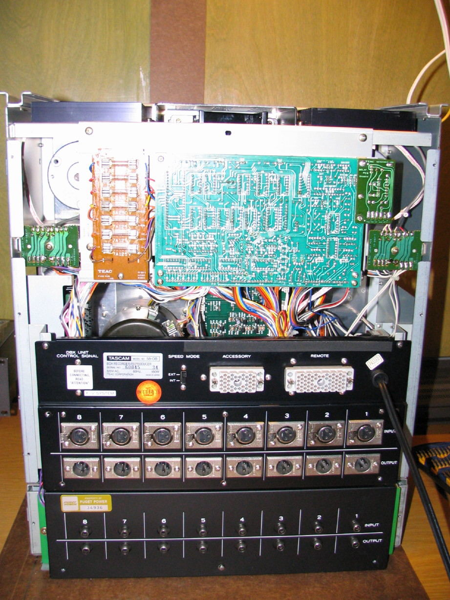
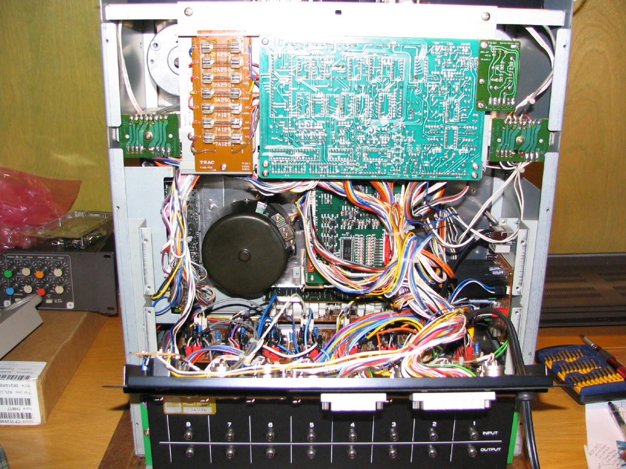
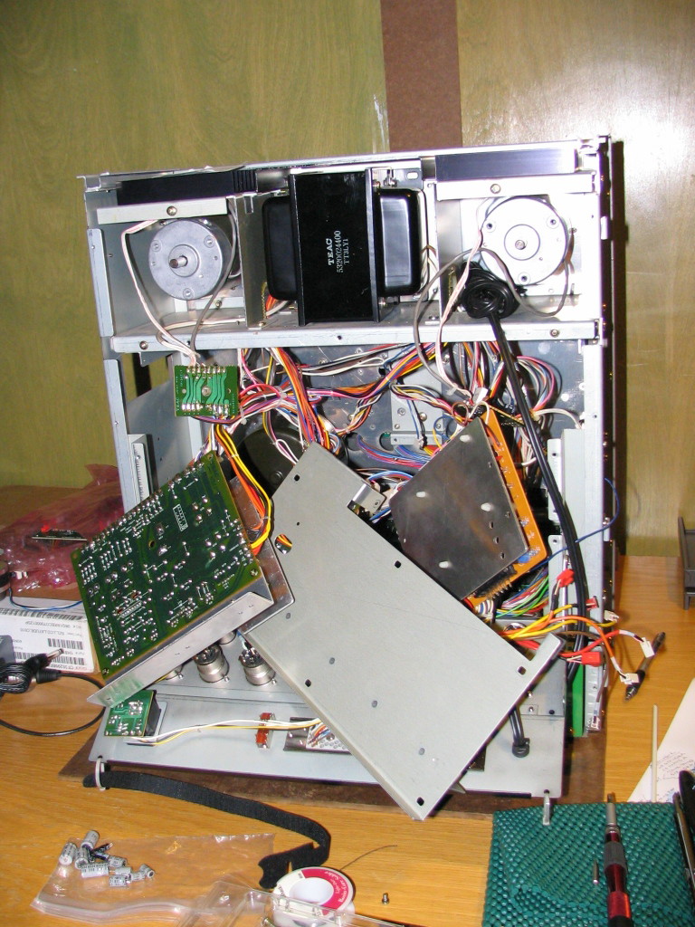
The 58 is coming back together nicely. Night before last I got all the PCB's reinstalled (except of course for the amp cards...leaving those out until everything else works, and then per evm1024's advice from long ago testing them one at a time...). I was honestly nervous about it because as I started to piece it together I realized how much my memory had faded as to what went where, which screws fastened what...that sort of thing. Fortunately for the most part I labeled plugs well, re-threaded screws into brackets and parts so that it was obvious what went to what, and had pictures to reference. The manual is, of course, essential too to double and tiple-check things. Looks like this now:
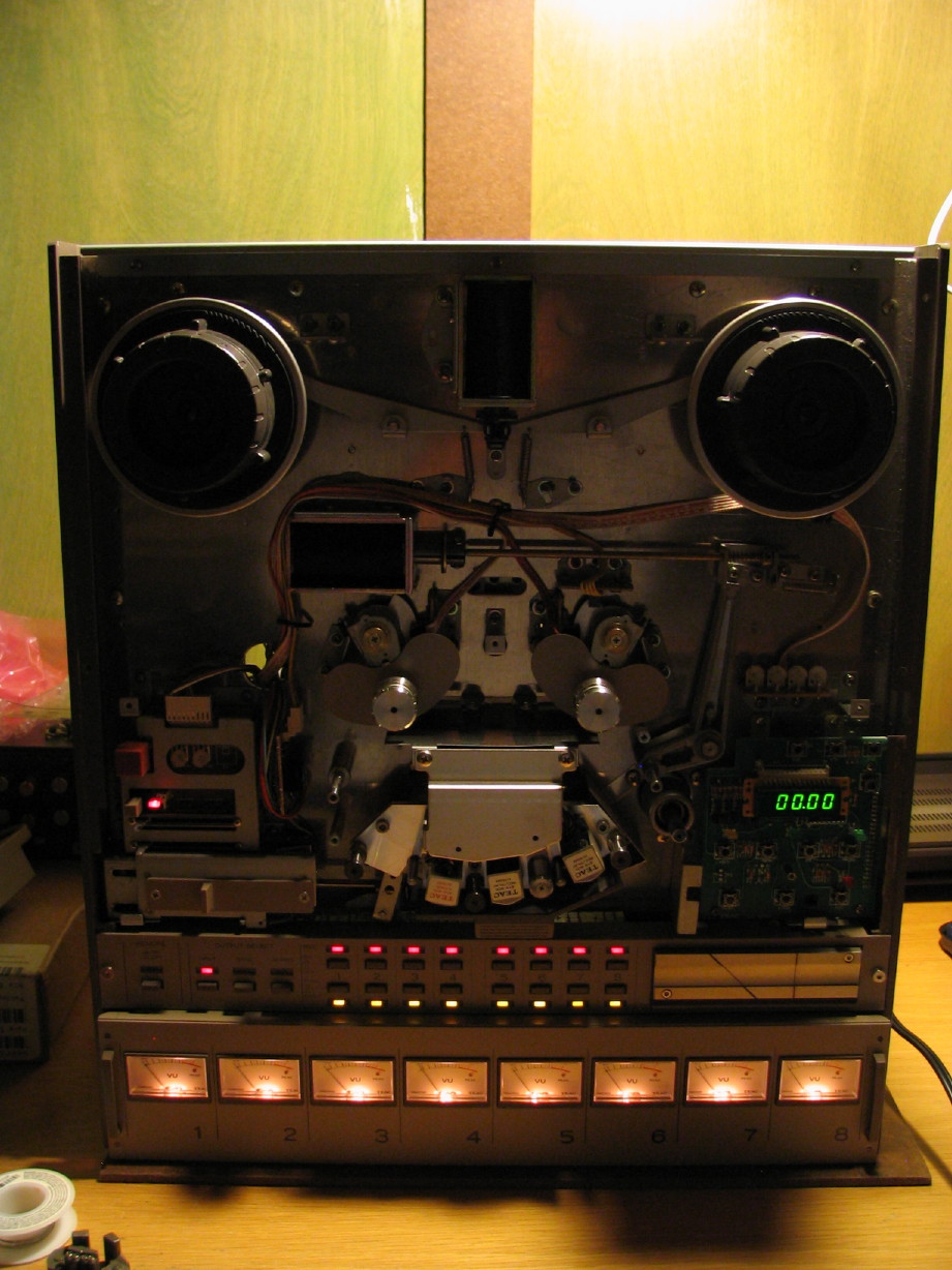
All the transport functions (except for one vital piece; more on that below...) operate wonderfully...all lights light up, reel motors are working nice and strong, solenoids are crisp...forgot how much I like the mechanical sounds of this machine. I'm really pleased with all that. I also confirmed how the tach roller comes apart and this would apply to the 52 as well:
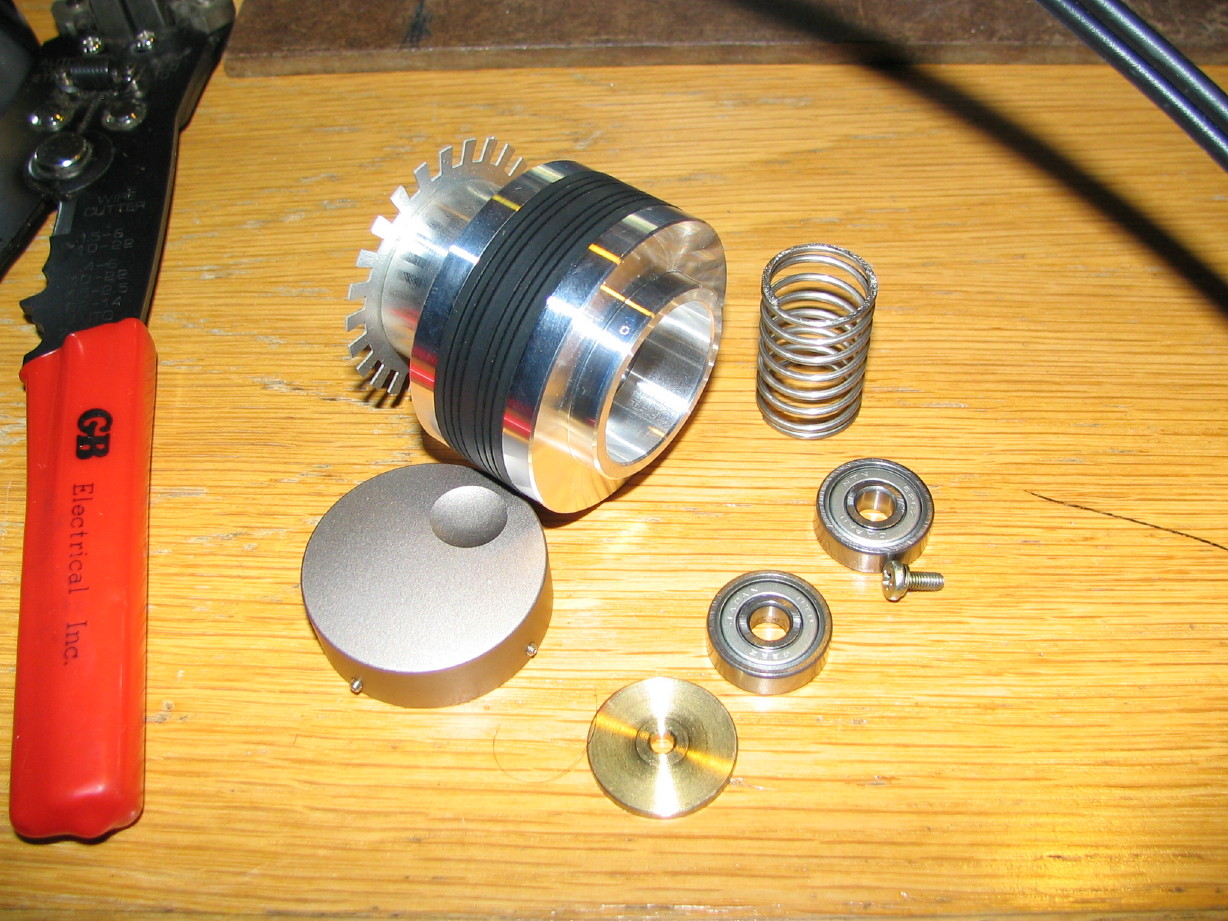
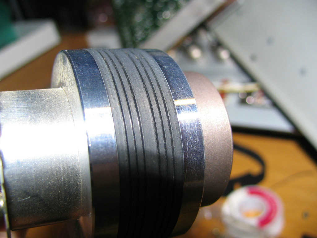
You need a 0.9mm hex key. I thought it was too big and my 0.7mm too small, but it is just a snug fit for the 0.9mm...may just be the thckness of the plating on my 0.9mm bit or the manufacturing tolerance but it worked. I have those bits as well as others in a neat mini-bit driver kit I got in a set a year or two ago and it has been a real boon to my toolbox. So there are two of those 0.9mm hex socket set screws in the roller cap (the one that has the dimple in it for manual scrolling with your finger), and once those are loosened the cap comes right off and what you see inside is a philips screw in the center holding a thick brass washer on. It goes together like the pinch roller...loosen the screw and remove it and the washer and behind that the first bearing gets pushed out by the spring that is in between the front and rear bearing. In order to get the roller off now you'll need to remove the tach sensor. You can get to the two screws that fasten the tach sensor to the deck plate...they are to the left of the sensor. If you don't remove the sensor it will restrict the removal of the roller because of the slotted sensor plate on the back of the tach roller assembly. Now you can pull the roller assembly off.
It is possible that you may not be able to get the rear bearing to come with the roller assembly. This is what happened to me. The rear bearing was on the roller spindle so snugly that it stayed on the spindle, and bearing OD is a tight squeeze through the ID slotted sensor plate. My sensor plate got slightly distorted but this shouldn't effect the performance of the tachometer circuit. I then had to use my little custom puller I made for reel motor bearings to get the rear bearing off the tach spindle. Its not press fit or anything, I just think, again, it might be a tolerance thing as it was really easy to get off using the puller. Usually if a bearing is press fit onto a spindle it will give a little *pop* when it comes free under the pressure of the puller. No *pop* at all here. So here are the parts:
So now I'll probably replace the bearings and try cleaning up the rubber a bit with conditioner as cjacek suggested.
So now for the bad news:
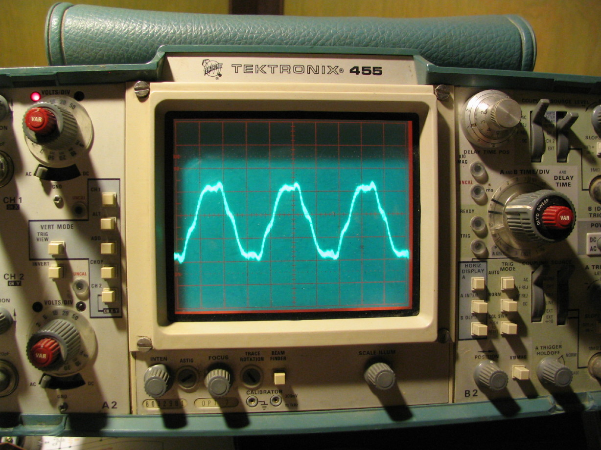
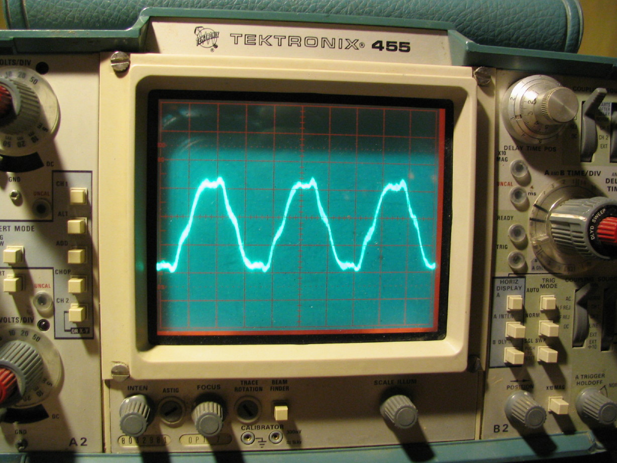
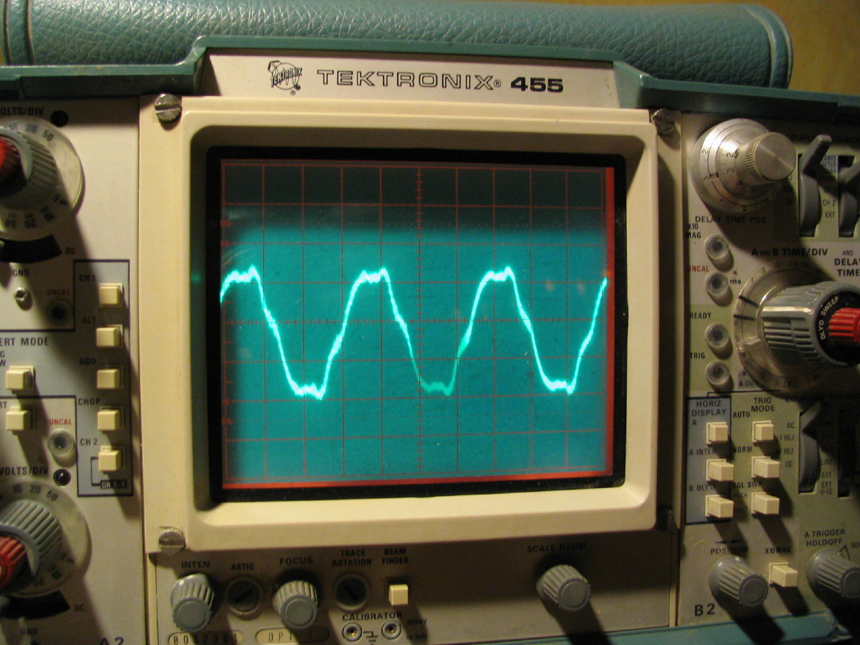
Something is gunny-sack with my capstan motor or on the servo board...

Used to be that when you powered the deck up the capstan motor gave this neat "brrrrrup" sound and quickly reached speed and then was nice and quiet. Now it goes "brrrrrrrrrrrrrrrrr", is spinning well below the correct speed if it spins up at all (sometimes I have to give it a spin with my fingers to kick start it). The pitch control function works. There is a funny clicking sound too when it reaches a certain speed. I think I used to hear that clicking when the capstan was under external sync control and when it was speeding up or down to lock to the timecode...
Here is a video of the problem so you can hear the sound (again, this is DivX encoded):
https://www.torridheatstudios.com/ftp/share/movies/Tascam%2058-OB%20Movies/MVI_2081-10.avi
Also, here is a pdf of the Capstan Servo PCB:
https://www.torridheatstudios.com/ftp/share/documentation/Tascam/Tascam%2058/Tascam%2058%20Capstan%20Servo%20PCB.pdf
I did check the voltages coming to the PCB and I
think they are okay, but a couple are high:
PIN 1: 4.9V (should be 5.0V...A-OK)
PIN 2: GND (A-OK)
PIN 6: 29V (should be regulated 24V...I
think that's okay...

)
PIN 7: 34.5V (should be
unregulated 24V...again, is that okay? Too High?
)
I
did recap the PCB so maybe that has something to do with it, or maybe one of the local regulators for this PCB got damaged when I put the extender card in wrong. That error did take out a 15V regulator in the PSU, so maybe something got damaged...dunno. Ideas?


 :rolleyes:") ; its called throw all the little packages in a box...takes a little time to dig through and find everything I need...I think I resist getting a little organizer unit because I keep telling myself that, for the most part, the recapping will slow down extensively at some point and I would ask that you all stop chuckling now.
; its called throw all the little packages in a box...takes a little time to dig through and find everything I need...I think I resist getting a little organizer unit because I keep telling myself that, for the most part, the recapping will slow down extensively at some point and I would ask that you all stop chuckling now.


")
")