You are using an out of date browser. It may not display this or other websites correctly.
You should upgrade or use an alternative browser.
You should upgrade or use an alternative browser.
MCI JH-416 Story...
- Thread starter sweetbeats
- Start date
sweetbeats
Reel deep thoughts...
Yah...
There's a blue lamp on each input strip too for when the channel is routed direct to the buss slot that the module is plugged into on the motherboard.
There's a blue lamp on each input strip too for when the channel is routed direct to the buss slot that the module is plugged into on the motherboard.
briank
analog for the people!
Man, now I need to double check...I think my 600 PSUs have blue jewel lights...Hey, it was the disco era...lol! (mine were made in '79, let's be glad they didn't end up on any baseball fields hehe...)
Yep, your PSU looks like the other MCIs I've been in, I knew you'd like 'em. The access cover is much like our JH-110's--the cover comes off to reveal test points for the +/-15 and 18v rails. The JH-110 and 600 audio PSUs have the slide-out "chimneys" with cinch and/or Molex connections and the black regulator heatsinks that slide out with the removal of a screw. I love it, so different from modern disposable gear...they're good designs made in an era when equipment was meant to be maintained and serviced by bespectacled bearded guys smoking pipes and cursing a lot
Sorry to see the bent rack ear...some people just don't "get" packing gear for shipping especially with this heavy old stuff...good news is the steel is thick enough that you should be able to bend it back without fatiguing it too much. Your PSUs look quite clean inside! My heatsinks and fans arrived "carpeted" if you know my meaning :rolleyes:")
Yep, your PSU looks like the other MCIs I've been in, I knew you'd like 'em. The access cover is much like our JH-110's--the cover comes off to reveal test points for the +/-15 and 18v rails. The JH-110 and 600 audio PSUs have the slide-out "chimneys" with cinch and/or Molex connections and the black regulator heatsinks that slide out with the removal of a screw. I love it, so different from modern disposable gear...they're good designs made in an era when equipment was meant to be maintained and serviced by bespectacled bearded guys smoking pipes and cursing a lot
Sorry to see the bent rack ear...some people just don't "get" packing gear for shipping especially with this heavy old stuff...good news is the steel is thick enough that you should be able to bend it back without fatiguing it too much. Your PSUs look quite clean inside! My heatsinks and fans arrived "carpeted" if you know my meaning
sweetbeats
Reel deep thoughts...
Brian, that was one thing that came with the $125 price tag of the supply was that the seller went through it and did a cursory cleaning and load tested it. Replaced a couple components and put a functioning fan on it so it is ready to go.
Maybe one reason I'm not "upset" but rather simply "disappointed" with the damage is that I assume anything I order that has any mass and size to it is going to come with some damage. Proper packing can certainly mitigate the risk almost entirely, but there is always risk no matter how well its packed. The disappointment is greater when the packing job is more poor because the damage could be avoided, but I know I've accepted risk when I buy something like that and have it shipped.
I should be able to straighten it out...
"Chimney"...I like that...")
Maybe one reason I'm not "upset" but rather simply "disappointed" with the damage is that I assume anything I order that has any mass and size to it is going to come with some damage. Proper packing can certainly mitigate the risk almost entirely, but there is always risk no matter how well its packed. The disappointment is greater when the packing job is more poor because the damage could be avoided, but I know I've accepted risk when I buy something like that and have it shipped.
I should be able to straighten it out...
"Chimney"...I like that...
briank
analog for the people!
"Chimney"...I like that...
That's how the MCI manuals refer to them. I like it too
P
pianodano
Guest
bespectacled bearded guys smoking pipes and cursing a lot
Hey, I resemble that remark
sweetbeats
Reel deep thoughts...
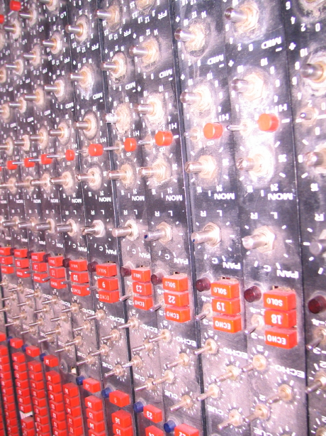
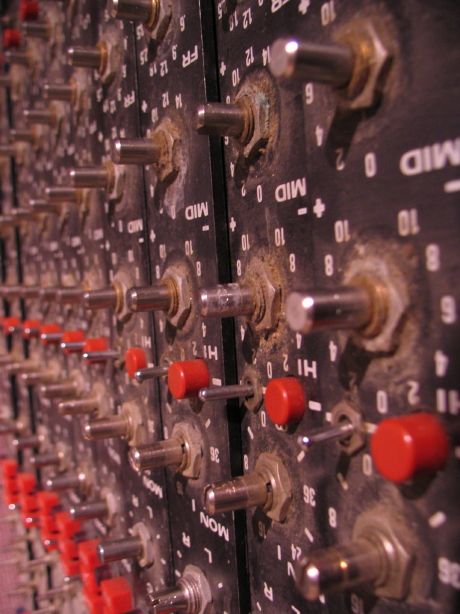
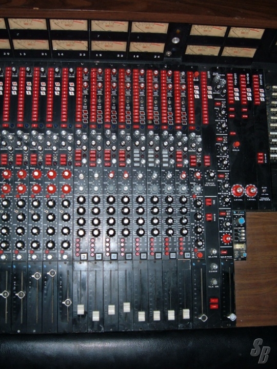
Here's how the modules sit right now, stripped of their knobs...some closeups too so you can see how nasty they are...these will make for good before and after shots:
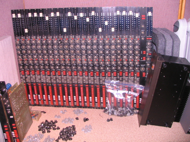
The Tascam supply sitting on the floor in front of them gives some perspective of the size of the strips since the supply is 19" wide.
The panels are supposed to be gloss black.
The Tascam supply sitting on the floor in front of them gives some perspective of the size of the strips since the supply is 19" wide.
The panels are supposed to be gloss black.
lo.fi.love
Functionally obsessed.
That is nasty!
Nice score on the MCI!
I don't know if you've seen these upgrade opamps or not, but they seem pretty neat. SE-DOT5™ RED and BLUE DISCRETE OPAMPS
The other thing I recalled reading was this thread: MCI JH 416 - how would you describe the sound? Any "equivalent" pre's? - Page 3 - Gearslutz.com
Something about the wiring of the meters screwing with the sound of the board.
briank
analog for the people!
Nice score on the MCI!
The other thing I recalled reading was this thread: MCI JH 416 - how would you describe the sound? Any "equivalent" pre's? - Page 3 - Gearslutz.com
Generally I avoid Gearslutz opinions on MCI gear like the plague because so much of them are a fresh steaming pile of bu!!sh!t
(like those guys who claim a 600 sounds clean and boring...uhh, compared to what, a chorus of foghorns??) but this comment made me smile! "In the end... She's like a Cuban chick. Big in the legs, medium waist, small on top... but if she's gotta good face to start with..., and ya don't treat her bad. She will MAKE YA SMILE.

Last edited:
sweetbeats
Reel deep thoughts...
Nice score on the MCI!
I don't know if you've seen these upgrade opamps or not, but they seem pretty neat. SE-DOT5™ RED and BLUE DISCRETE OPAMPS
The other thing I recalled reading was this thread: MCI JH 416 - how would you describe the sound? Any "equivalent" pre's? - Page 3 - Gearslutz.com
Something about the wiring of the meters screwing with the sound of the board.
Yes. The BOVA discrete amps seem to be quite favored by those that want to keep character but improve on the noise factor. People seem to really like the sound, but at $59 EACH they are good for selective upgrades like in the master summing buss and such. Would be neat to try but down the road a far piece but doing the whole mixer would cost about $10,000. 5532/5534 chips are a popular mod too as they stay true to MCI, are cheap and are a good chip but the power rails have to be scaled back...and its not even worth thinking about for me at this point as I don't even know what the stock MCI 2001 opamps sound like...I may love it, and I have spares of them since I'll be short-loading the frame.
The "wiring of the meters" is a long-standing issue and I'm not sure what to make of it. Its not the "wiring" per se but the fact that the meters are unbuffered and therefore there are measurable distortion artifacts that enter the audio path. This is true of the Ampex 440 electronics as well since the meters are unbuffered there...all the MM series machines as well (i.e. MM-1000, MM-1100 and MM-1200). I recently read something though that gives pause for consideration:
"I'm not an expert in the Master Munchers because I've never had one, but as far as I know, and I have a few MM-1000 electronics units, the MM-1000 used GOOD meters -- the same as the AG-440(A) and B use -- and they DON'T NEED buffer amplifiers because the meters in THESE are based on Jay McKnight's VU meter design ( originally designed for the MR-70 ) that use copper oxide rectifiers that have very low turn on voltage drop.
I know even less about the MM-1100 and MM-1200, but I know that the AG-440C (which is about the same era) uses some CHEAP meters that do NOT use the copper oxide rectifiers, and they DO need buffer amplifiers (which Ampex DIDN'T use on the AG-440C either!) THAT is ANOTHER fault of the AG-440C!
IF the MM-1100 and MM-1200 use those meters, they will need buffer amplifiers too (or should have them -- whether they actually used them or not, I have no idea). [they did not]
Anyway, there is absolutely no point in putting buffer amplifiers in the MR-70, the AG-350, the AG-440, the AG-440B or the MM-1000. The bottom line is if you have one of these, DON'T be bluffed into thinking you need buffer amplifiers on their meters. It won't accomplish a thing.
Incidentally, if you have one of these, and you DO hear some distortion that changes when you switch the meter and output switch from reproduce to record, CLEAN THE METER AND OUTPUT TRANSFER SWITCH CONTACTS!! Just spraying them with WD-40 and working the switch several times works fine. The first time I heard all the fuss on this list about these "buffer amplifiers", I listened carefully to my AG-440 while changing that switch, and I DID notice a difference. Then I sprayed the switch with WD-40 and the difference went away COMPLETELY. Dirty switch contacts caused the distortion on the AG-440, the meter did NOT!
(Again, no comment is made about the MM-1100 or MM-1200. I've never had or even seen one of these. THEY depend on what meter they used, and I have no idea what that is.)"
I have to add this footnote too before somebody goes running off saying The MM-1100/1200 meters have to be buffered or the world's gonna end!!!!"
 How many reference-grade recording projects were done on MM-1100 and especially MM-1200 machines? The MM-1200 is a legendary machine. Seems like unbuffered "cheap" meters (relative to the Dixon meters, according to the individual quoted above) didn't get in the way of the MM-1200's reputation...I guess it still sounded alright in spite of the absence of a buffer amps for the meters, though Ampex DID incorporate buffer amps for the meters in the ATR-100 series.
Anyway, the meters in the JH-400 series are these same meters as used in the AG-440, AG-440B and MM-1000.
On those tape machines you can test the difference that the meter makes by switching the input select paddle to "BIAS" while monitoring an input source as that takes the meter out of input the circuit. Nice way to A/B the meter impact.
I personally will be trying this at some point as well as the suggestion to clean the contacts.
If I hear a difference that is toublesome, and if cleaning contacts doesn't fix it, then I will either build buffers (for which I have a schematic) or I also have a potential source of pre-fab purpose-built PCB's that hang on the Dixon meters with a parts list for stuffing yourself. They will be designed for the AG-440/440B/MM-1000 with relay circuitry to effect a hard-contact bypass when the machine is switched to BIAS mode, but that switching circuitry could be left out and jumpered as needed for the JH-400 meters.
The BIG POINT I want to make here with all this buffering stuff is that *somehow* all those AG-350, AG-440(A)/B/C MM-1x00 machines and MCI JH-400 series desks produced (figuratively speaking) countless hits without buffer amps on the meters. I say its not worth messing with them unless you can pinpoint the meter distortion as the cause of an undesirable/unacceptable element in the audio path. Unless you just can't handle the idea of something like that existing in the audio path...but clearly there are opinions on both sides.
I'm a gearslutz.com lurker as well. I'm not sure there is a good philisophical fit there for me which isn't anything of a wrong/right issue...just not the right fit.
Last edited:
sweetbeats
Reel deep thoughts...
Oh I am so screwed.
So any of you that have been around here for awhile know I have the unfortunate habit of picking up vintage mixers that are missing the power supplies.
Remember this one? No supply, after much effort I tracked it down sans interface cable...interface cable with unobtanium connectors...global search, found some in the UK.
And how about this one? Another Tascam, one of a kind, no supply or interface cable, and no schematics or support...figured out what rails were needed and with much help modded a PS-520 power supply (that I was fortunate to find), tracked down the "you'll never find it" connector at the mixer end of the cable and the rest is history.
Now I get this MCI beast. No supply. I think I'm doing pretty good tracking down a supply within fairly short time of getting the mixer. But I've been baffled by the interfacing between the power supply and the mixer...things aren't adding up...not making sense...and then I realize I'm totally missing the forest for the trees. The answer is right in front of me in the manual...I just didn't consider it could be the case...I don't need just one of the power supplies I now have...I need three! Yes, each zone of the mixer (i.e. audio, relay buss, lamps) is powered by its own beefy 24VDC bipolar supply. Yes folks, the JH-400 mixers are powered by a 9U array of power supplies.
Oy.
I've GOT to stop buying mixers without power supplies.
briank
analog for the people!
Holy crapoli, seriously? THREE? Oh man! My 636 uses two...one handles the phantom power and a couple 18vs for each side of audio, the other handles lamps, logic and automation...I never in a million years would have guessed you'd need three for a 416(!!!) Egads! Have you looked into buying some kind of modular supply to make this happen (rather than another original supply)?
RICK FITZPATRICK
New member
Ditto!! I haven't owned a new car since '78. Even if I could, I'd NEVER buy a new car again. And btw...what is this "...work on...contemporary vehicle." I was under the impression newer vehicles can be "shut down" via satellite if you so much as open the hood.but so is my old Chevy truck and I'll work on that any day as opposed to a contemporary vehicle.

Oh, good luck with this project too!
sweetbeats
Reel deep thoughts...
Holy crapoli, seriously? THREE? Oh man! My 636 uses two...one handles the phantom power and a couple 18vs for each side of audio, the other handles lamps, logic and automation...I never in a million years would have guessed you'd need three for a 416(!!!) Egads! Have you looked into buying some kind of modular supply to make this happen (rather than another original supply)?
Yah...heh...urg.
I believe the logic in having three identical supplies in spite of the fact that one of those supplies is OVERKILL for just the lamps, is for backup. The power supply behavior is somewhat dictated by the cable plugged into it going up to the mixer (depending on what is jumpered in the connector) so when you plug in the cable specific to the lamp buss in the console it engages a couple auto-voltage trim circuits in the power supply to scale the rails back from 24V to 21V or 22V to extend the life of the lamps. The handy bit here is that lets say you are in the middle of a session and something goes kablooey on your audio supply or relay buss supply...just pull the cable from the lamp supply and move the connector from the bad supply to the lamp supply and you are instantly back in business. You'll have to limp without VU lamps or SOLO lamps but it would be doable until you could get the bad supply repaired.
I'm definitely going to try and get at least one more of the MCI supplies and if I can't track down a third then I will build up a modular supply for the lamp buss.
The cooling fan on the MCI supply is pretty quiet, but get three of those going along with the two (noisy) fans in the MM-1000 and the capstan motor racket and the studio is going to be a noisy place. Gonna have to deal with that.
1 down, 1+1 to go.
briank
analog for the people!
Yah...heh...urg.
I believe the logic in having three identical supplies in spite of the fact that one of those supplies is OVERKILL for just the lamps, is for backup. The power supply behavior is somewhat dictated by the cable plugged into it going up to the mixer (depending on what is jumpered in the connector) so when you plug in the cable specific to the lamp buss in the console it engages a couple auto-voltage trim circuits in the power supply to scale the rails back from 24V to 21V or 22V to extend the life of the lamps. The handy bit here is that lets say you are in the middle of a session and something goes kablooey on your audio supply or relay buss supply...just pull the cable from the lamp supply and move the connector from the bad supply to the lamp supply and you are instantly back in business. You'll have to limp without VU lamps or SOLO lamps but it would be doable until you could get the bad supply repaired.
I'm definitely going to try and get at least one more of the MCI supplies and if I can't track down a third then I will build up a modular supply for the lamp buss.
That all makes sense! I'm still surprised by that console's PSU needs, though! Now, granted, the 600's two supplies are each chock full of giant 10,000uf caps and a chunk of iron the size of my head lol...but it's a bigger and more electronically complex console, so when I saw the photos of the supply you posted for the 416, it seemed perfectly reasonable that it would power that desk. Oh well! You'll still end up with a seriously cool console for what cash you put into it, after the supplies and refurbing it will still be a real steal!!
The cooling fan on the MCI supply is pretty quiet, but get three of those going along with the two (noisy) fans in the MM-1000 and the capstan motor racket and the studio is going to be a noisy place. Gonna have to deal with that.
Oh I hear ya there...the other day I was archiving some tape tracks into ProTools and monitoring through the console...two fans in the console's audio supply, another identical fan in the tape machine's power supply, and the ProTools computer and interface whirring away...egads, "I think I'll juice up the monitors a little more..."
sweetbeats
Reel deep thoughts...
That all makes sense! I'm still surprised by that console's PSU needs, though! Now, granted, the 600's two supplies are each chock full of giant 10,000uf caps and a chunk of iron the size of my head lol...but it's a bigger and more electronically complex console, so when I saw the photos of the supply you posted for the 416, it seemed perfectly reasonable that it would power that desk. Oh well! You'll still end up with a seriously cool console for what cash you put into it, after the supplies and refurbing it will still be a real steal!!
Well I certainly think so (that it will be a real steal), but I might be biased.
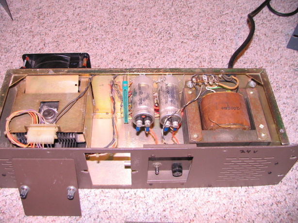
And as far as the power supply, yeah I recall my first reaction when I opened it up and saw the filter cap value and I thought "huh that seems kind of on the shy side" but the main transformer looked up to the task...the transformer alone must weigh 20lbs. I think the only thing I've got that comes close is the tranny in the transport power supply for my Ampex MM-1000, but I digress.
I guess with the size of the transformer and the 18-pin output connector, and the fact that I'm unfamiliar with any mixer power supply conventions aside from internal or a single external unit it just never crossed my mind that there would be multiple supply units...even though I've read "Three interchangeable power supplies are used" on the spec sheet I don't know HOW many times! Duh.
Interestingly enough though it appears that the relay buss in the mixer is the biggest power hog, significantly moreso than the audio buss, and I'd think the audio buss would be of relatively high demand with the relatively high power rail voltage and +4dBu nominal standard throughout the signal path, though the MCI 2001 opamps seem pretty thrifty on current draw (2mA at idle) and there are only five per channel, and then the master section...but anyway, I certainly WISH it was all in one box but I also like the idea of the relay buss being powered completely separately from the audio buss. One of those supplies for the lamp buss is *DEFINITELY* overkill, so that was just a convenient redundancy feature in the event of a failure, which I like. I'll be increasing the filter cap value and may voltage, upgrading the bridge rectifier, replacing the electrolytics on the regulator card and building a soft-start circuit.
I started thinking about the fact that my power supply is brown instead of black. Looks like my supply is from the 428/440 era...essentially the same supply but just laid out toally different. First another picture of mine, and then a pic of a rack of 416 black supplies (note that the middle one is racked upside down)...
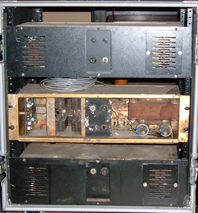
Yes, I probably will paint the brown black..."I want it painted black."
So here's some fun information, or "What model IS it??"
I've been trying to nail down just what version of JH-400 I have here. There were two versions of the 416, the 416"A" (officially called just "416") and the 416B...then there was the 428 and 440 (also now retroactively referred to as the "A" version) and the 428B and 440B.
I've been operating on the understanding that mine was a 416 *something*, definitely not a 428 or 440, but I was getting several conflicting opinions on what it was mainly because of the bussing assignment features. I've explained this earlier but the way my mixer appears is that there are a total of 24 subgroup summing busses, and that input modules 1~16 can be assigned to groups 1~16, and input modules 17~24 can be assigned to groups 9~24...that's the way the assign buttons are marked...channels 1~16 have buttons 1~16, and channels 17~24 have buttons marked 9~24. Additionally each input module can be direct assigned to the group that numerically corresponds to the slot in which it is installed (i.e. when you hit the direct assign button the output of channel 1 is routed to group 1, 2 to 2, 3 to 3 and so on). That's the way it looks on mine. The trick is that that was a feature that didn't come until the 416B, and maybe late in the run at that...not positive but that's my understanding at this point. The way I read it is that the 416"A" also had 24 groups but all 24 channels could only be assigned to groups 1~16 and the only way to access "groups" 17~24 was through the direct assign switches on channels 17~24...so 17~24 weren't really summing busses but rather switcheable direct outs tied to their respective input module. So, okay...according to the assign button labeling that would make mine a 416B...to confuse matters mine has the P&G faders which came with the 416B as opposed to the backlit API faders on the 416"A", AND mine has mid-band eq that is switcheable for boost OR cut (416"A" was boost only in the mid-band)...so my point is that I've got 416B issue P&G faders, eq with mid-band boost AND cut which is also 416B and apparently I've got summing features not available until the 416B, but then I've got some saying its an "A"...even have somebody contesting its a 428"A" but I'm confident it is not (many, many control surface features on the 428/440 desks not present on mine, 56-point patchbay modules as opposed to 48-point, and most notably 28 input module slots on the 428 as opposed to 24 on mine...dead giveaway...wrong color scheme too). So I believe I've nailed down that it is indeed a 416"A".
As far as the faders: it looks for sure like all my faders were updated to the P&G faderpacks at some point...all the solder joints are non-factory, and I can see where an additional ground used to go from the pack, presumeably for the back-lighting on the API packs. As for the cut function on the eq mid-band: though the job was very nicely done to add it on mine, I believe it is indeed a mod done by the factory or by a previous owner...looks like it used to be just boost only. There is some hand-wiring evident because the PCB doesn't accomodate the inversion circuit. Annnnnnd the summing issue?: Well, I looked at the serial numbers of all my input modules. Sixteen of them range from about 865 to 899. Then 8 of them range from about 1050 to 1075, so I figure the console came out of the factory short-loaded at sixteen inputs and inputs 17~24 were added later. It may be that the owner, for whatever reason, specified the marking of the assign buttons on inputs 17~24 to be 9~24 even if they only route to groups 1~16, OR maybe that's all they had available...dunno for sure. Or maybe my console is a freak "A" and does have the later pseudo 24 summing busses (which is what I call it since it is really more like 16 + 8 since inputs 1~16 don't have access to groups 17~24, and inputs 17~24 don't have access to groups 1~8...) I'll have to do some studying of my console's motherboard at some point which will answer the question, and I'll have PLENTY of opportunity to studdy when I get to soldering up new harnessing.
The bottom line is that after reviewing the evidence and doing further research (like for instance that the 416"A" frames had five 48-point patchbays for a 240-point patchfield, and the 416B had six of them for 288 points...I've got five bays...) I think its undeniable that mine is a 416"A" which were made from about 1971 to 1972.Here is a 416"A" console that was up for sale some time ago that was originally short loaded with 16 "A" input modules and then modules 17~24 were added later but insted of adding "A" modules they are B modules...you can see them side-by-side and the B modules are very different...the mic amp trim is up top of the strip by the subgroup master trim knob on the B, whereas on the "A" modules the mic amp trim is down above the fader...the B modules have a big white channel mute switch right above the fader, as well as a number of additional push switches for various functions. The pics also show the difference between the API fader knobs and the P&G's. Anyway, the modules on 1~16 are like mine..."A".

Last thing to comment on in this post is that I have a hardware solution on the way for my missing patchbays. My wiring conundrums are in three chunks:
- all internal wiring is missing...need wire...a lot of it
- the factory punchblocks are not really the best as they are designed for solid wire not stranded, and mine have been bunged up because somebody decided to solder on them, probably to try and address problems they were having due to the fact that they are designed for solid wire and not stranded...replace blocks...
- my 240-point patchfield is only 48...need to obtain replacements for the 4 missing bays
Recall I recently got those ADC 96-channel audio-grade punch panels to replace the punch blocks, so #2 is taken care of in a big way. Now I've addressed #3. It'll take some fabbing but I couldn't beat the price...I think no matter what I'd have to have some faceplates fabbed or something because finding half-width TT patchbays? Forget it. But there are a number of ADC full-width patchbays out there that have jacks mounted to blocks and the blocks mount to the faceplates. That's the way the one patchbay I have is setup...so you can get a full-width bay, remove the blocks out of it and then just have custom faceplates made up on which to mount the blocks. I was thinking I'd have to spend $100's to get the hardware and then STILL have costs in custom fabbing.
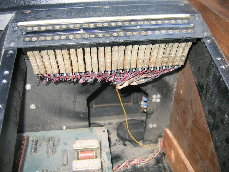
See, here's the module I have...notice how there are two jack blocks of 24 points each in the module:
Well, I got this one...its ADC, the jacks match and everything...
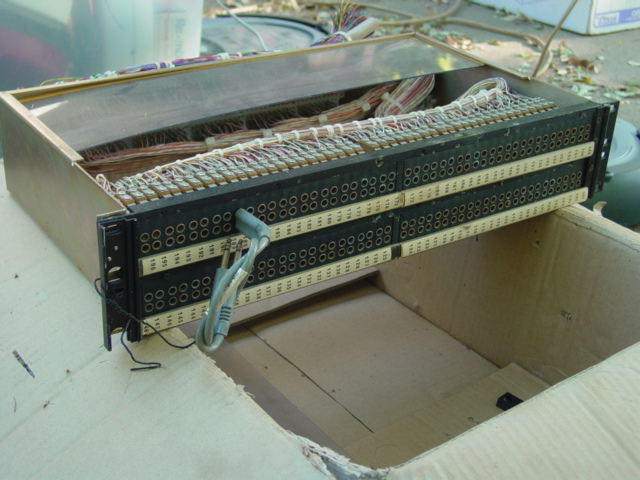
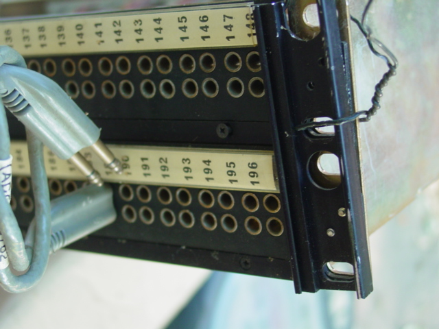
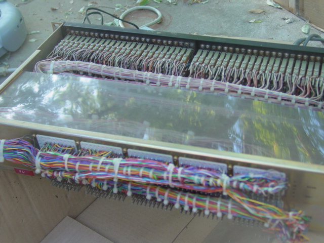
the configuration of the jack blocks is a little different in that each block has 48-points rather than 24, so rather than a 24 x 10 patchfield it would be a 48 x 4 + 24 x 2...but philisophically that works for me because four of the five patchbay modules are normalled anyway on the 416 (i.e. 24 group outs to 24 tape machine inputs, 24 line inputs from 24 tape machine outputs, 24 preamp sends to 24 line returns (inserts), etc.) so those four modules will have their jack sets "together" because they're normalled, while the last one, the one I have, is non-normalled and connects to the "tie-lines" (inputs to and outputs from external equipment not normally connected to the console inputs and outputs) and those will be separate blocks because they aren't normalled. Phew! That was CLOSE!
Notice that it terminates on a wire wrap panel on the back...don't think I have a need for that, but the bonus is that might give me some good quality wire I can salvage to minimize my expense for wire.
So what did I pay for it? $29. THAT was a good deal. So $50 for the three ADC punch panels and $29 for the ADC 192-point patchbay. Wire is probably going to cost well over $100, so having found the other components for as low a cost as I did is a real help.
Yes...I know I could easily save the fab costs and just use patchbays external to the console, but there is just something about the look of an integrated purpose-built TT patchfield on a mixer...always wanted a mixer with that, so I'm going to make it happen. PLUS...I betcha it'll be cheaper to have faceplates fabbed than to pay for the mass trunk of wire I'd need to mount the patchfield in an external rack...And the less wire the better anyway.
sweetbeats
Reel deep thoughts...
Well, that answers that. Just looked at the motherboard and it is clear that from the factory all 24 module bays bussed to groups 1~16 and "groups" 17~24 were only accessed directly via the direct assign switches on modules 17~24, but mine has been (poorly) modded so that modules 17~24 sum to groups 9~24.
No mysteries remain...I have a JH-416"A".
No mysteries remain...I have a JH-416"A".
briank
analog for the people!
Glad you got it worked out. I'd been curious if it was a late "transitiony-period" 416, a custom order (MCI seemed happy to oblige special requests), or just modded by subsequent owners.
They make console install and extra-special pain in the a$$, but there's something to be said about built-in patch bays. I'd never thought much about it before, but I'm definitely enjoying the one in my 600 series. Very nice to have everything right there and lots of patch points normalled to the console's insidey parts for easy, flexible routing. They do look cool too, but there's no mistaking their functionality.
It's a bonus that you don't have to deal with any freakin' Tuchels!
Yes...I know I could easily save the fab costs and just use patchbays external to the console, but there is just something about the look of an integrated purpose-built TT patchfield on a mixer...always wanted a mixer with that, so I'm going to make it happen.
They make console install and extra-special pain in the a$$,
but there's something to be said about built-in patch bays. I'd never thought much about it before, but I'm definitely enjoying the one in my 600 series. Very nice to have everything right there and lots of patch points normalled to the console's insidey parts for easy, flexible routing. They do look cool too, but there's no mistaking their functionality. It's a bonus that you don't have to deal with any freakin' Tuchels!
Last edited:
sweetbeats
Reel deep thoughts...
I think I'm going the route of getting some used Power One modules to power the JH-416...I found a great deal on six 24VDC 12A modules from a single source...they'd be about $300 shipped for all of them but they'd be great, beefy clean power for the console and relatively affordable considering what I'd likely pay for another set of the MCI power supplies, and then assuming they'd need some work. The Power One modules would just be wired back-to-back in pairs to create three bipolar supplies.
So that's what I'm thinkin'.
Comments?
12A overkill? Definitely for the lamp buss but I'd have the redundancy MCI intended with the three identical supplies...
[EDIT]
The Power One model number I'm lookin' at is F24-12-A
Tight regulation, low ripple and the recovery seems...really good...+/-0.02% deviation and 50ms recovery for a 50% load change...