P
pianodano
Guest
The site above shows several of the Ampex machines with his improved electronics. Nice pitcures of the 416 console also.
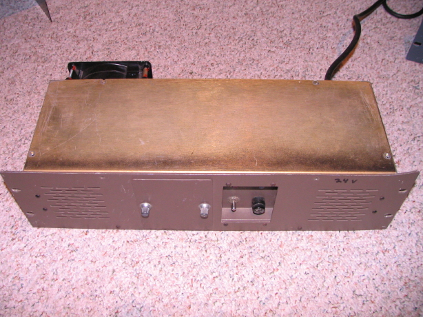
Yeah, Mr. Harned's ideas did go lots of places, but Its interesting to note that the first series of open reel machines they produced looked an awful lot like Ampex 440 fare. In fact the amp cards are interchangeable, as are the electronics power supplies. Hmmm.
"I got into the tape recorder business in an interesting way. I had built a console for Sidney Nation of King Records in Cincinnati and he, Mack Emmerman, and Bob Richardson had a bunch of Ampex 350 tape recorder with transports that still ran well, but electronics that were on the verge of quitting completely. So in 1968 Sid, Bob and Mack got together and hired me to design and build some new "solid state" electronics for the old transports. My electronics proved to be quieter, had lower distortion, and they didn't have the 'Bias Rocks' common to so many earlier designs.
"I filled this order for 100 units and I thought that would be the end of it, but when the word got around the industry that there was this guy in Florida building these 'solid state' electronics, a lot more people became interested in them. All of a sudden I'm sitting there looking at orders for two of three hundred of these things. People bought my electronics to use with the older transports, and we continued to sell these for several years. And that's where it all started for MCI in the tape recorder business.
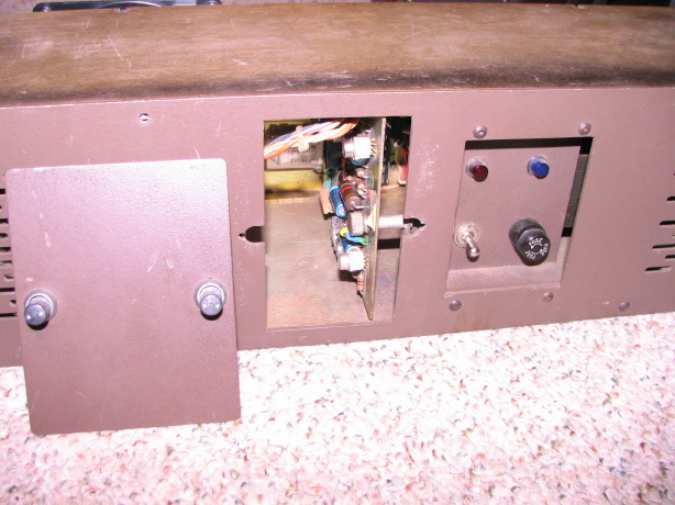
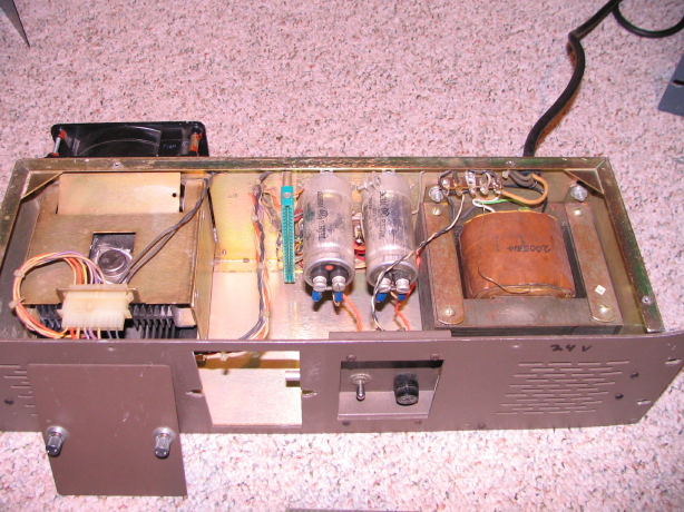
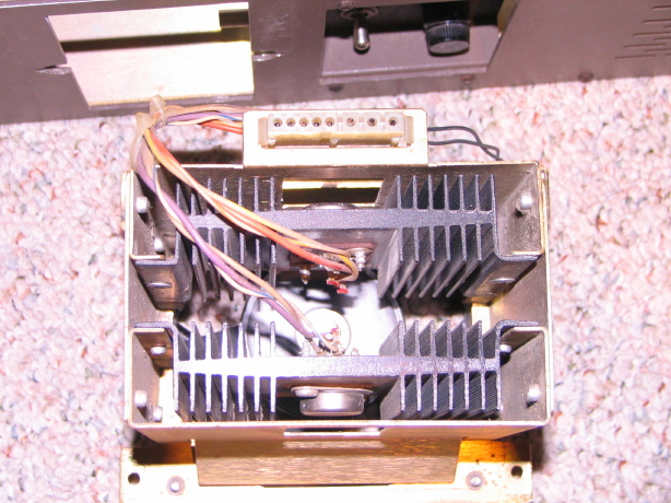
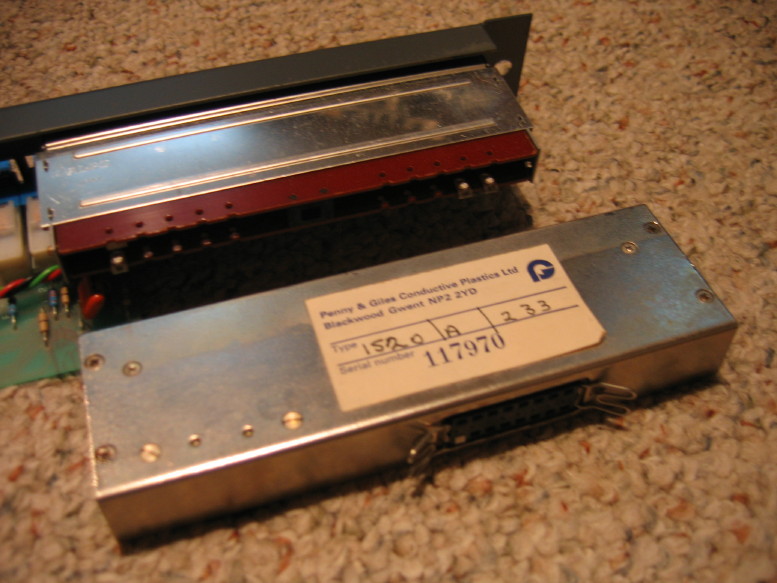
 It actually looks quite a lot like our JH-110's PSU.
Yep! 2N3055, assuming it was the pass transistor that was bad (he said the +24V rail was down when he first tested and found a bad transistor and I'm assuming it was the series pass for the +24V rail that was bad).
 Cory, you're completely insane.
I couldn't help myself

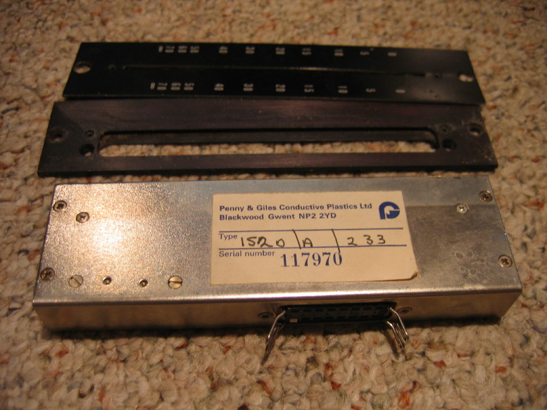
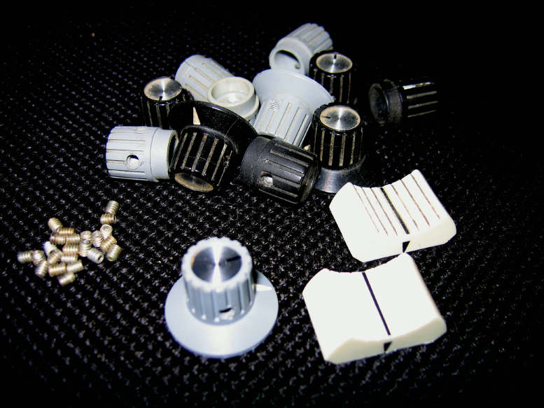
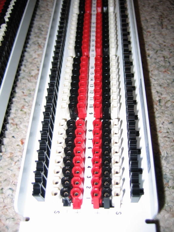

Holy macaroni, those are cool lookin'! Glad to see the progress on that console!
And how! Soldering Tuchels took me AGES and I still have some non-essential ones to do when time permits...your system looks more pleasant/less tedious for sure! Your re-cap will be much less of a PITA too! I envy the simplicity of that 400 on several levels!
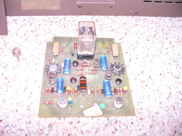
But, yes, recapping will be relatively painless as will troubleshooting. Who knows how it'll be sonically, and certainly I'll be without some typical control surface conveniences...notice there are no lo-cut filters, phase switches, phantom enable switches...its pretty bare bones...but so is my old Chevy truck and I'll work on that any day as opposed to a contemporary vehicle.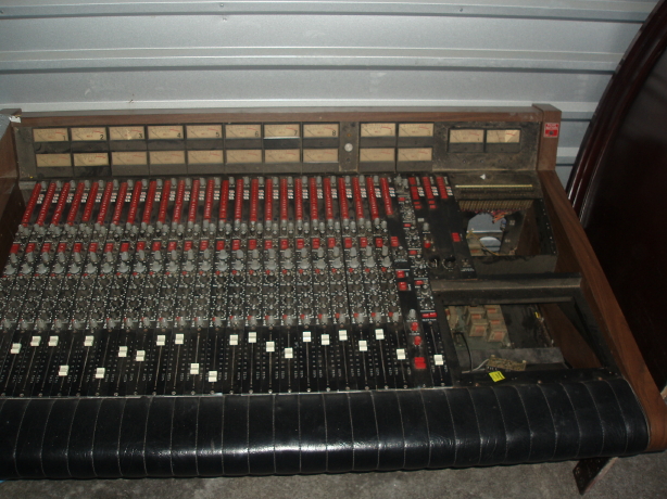
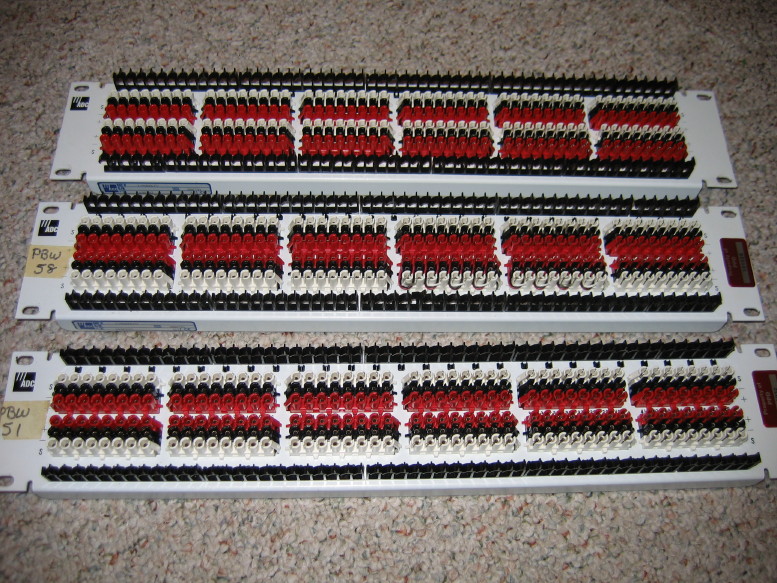
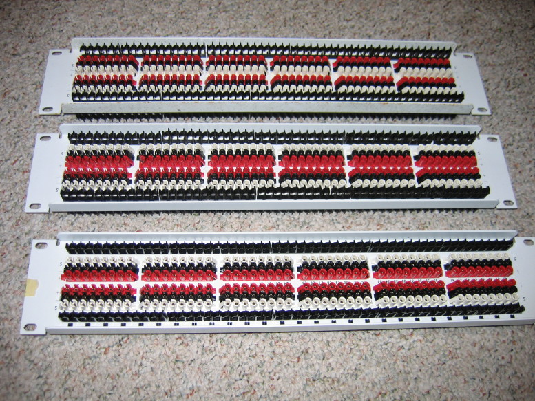
Well, I'll have the pleasure of soldering up the entire patchbay and motherboard...
") ) when you get it to the point that you can power it up and run some signal through it.
) when you get it to the point that you can power it up and run some signal through it.