Yamaha AX-500u

Tremaine

Chancellor of the EOPA
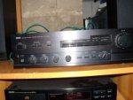
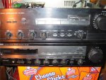
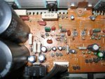
I recently aquired a Yamaha Natural Sound Stereo Amplifer AX-500u, 120V 370watts 460VA 60Hz.
and yes its got issues or i wouldnt be posting here.
when i plug it in, and turn it on, everything light ups, and it gets very warm, in a short time <10-20 min>.
the problem: theres almost no sound comming out of it. a little bit bleeds out the right speaker, and none out the left, the volume works, it just never gets loud. balance works <fades right in and out>.

i got another Yamaha RX-330 for parts that i got off the side of the road, with the cover off, i never pluged it in.

any ideas/suggestions from the great do it yerselfers, rescuers of countless forgotten peaces of gear, and mysterious mad scientists, immune to the effects of lead based sodder burns.

im looking for pics and scamatics now.

Thanks dudes.
 
Heres crapy pics i stold off the net.
 

Attachments

  • Yamaha AX-500u front.jpg
    Yamaha AX-500u front.jpg
    10.4 KB · Views: 955
  • Yamaha AX-500U Back.jpg
    Yamaha AX-500U Back.jpg
    11.2 KB · Views: 956
the volume knob spins counter clock wise to go up <thats gunna be bad someday> thats the way the numbers go. but at max volume theres no sound, at min theres a little, very little.

pluged it in, found a hot spot, burnt resister. i see another one with the same colors nearby. can i test the matching one while is pluged into the board and get an accurate reading with my multimeter? i

m looking for Schematics, found the manual.

will i need to change the parts around the burnt resister?
 
You have to remove at least one leg of the resistor from the PCB to measure it properly .....

Does the amp use a discrete Circuit or does it use a Chip ?? Is the Burnt resistor a small little 1/4 watt one or a Bigger 5w type ??

How about a Picture of the inside of the amp ??
 
Does the amp use a discrete Circuit or does it use a Chip ??

the manual says ALA <absolute linear amplifacation> circuit.
does that answer the question?

Does the amp use a discrete Circuit or does it use a Chip ?? Is the Burnt resistor a small little 1/4 watt one or a Bigger 5w type ??

its about 1/4 long, i drew you a pick of how it sits on the board. nice eh?

i looked at some 1/4 watt picks and im gunna say its a 1/4 watt resister thats blown, thou its on the bigger side.

i'll try to a get hold of a kamera.
 

Attachments

  • resister.jpg
    resister.jpg
    5 KB · Views: 924
absolute linear amplifacation Doesn"t mean a Thing as to if it is Discrete or a Chip .... Inside the amp there shopuld be a Big heatsink , Attached to that Heatsink will either be a Bunch of Large Power Transistors (they have 3 legs) or it has a number of Big Chips that have several legs ....

I bet it is a discrete circuit as I have a simular Model Yahama Reciever (5.1 setup at 65w per channel and 130w for the Sub) ......

Haveing very little output Volume and heating up quickly in a Discrete curcuit points to blown Output Transistors but it could be anything ......

Discrete amps are much harder to troubleshoot unless you have a Scope and an audio probe ..... Try testing the speaker output for DC , blown Output transistors will usually cause there to be a Lot of DC at the output ......

Generally when I get a busted reciever if I cant fix it in a couple hours I give up and Gut it for parts ......


Cheers
 
their transistors, 4 of them.

85W + 85W Chan A & B
no bass chan
but its got an effects loop.No radio eather, witch is cool. and two tape record outs.
5 line ins, plus phono, and a direct cd button to bypass the on board eq.
its cool.

and it almost works...
i'll test for DC and pull the resistors tommorow, one case its burnt, and the other half way to test it, case its a match.

how do you test it? one end disconnected and ohms on the multimeter, witch ends positive the free one? and it should read .25 or 25 ie. 1/4W?

im sorry dude, for asking questions i knew the answers to, i got into this far enuff to see its gunna take me 20 years to learn anything, so i kinda took a step back, i got a book thou, on electronics, looks like it was typed from the 50's.

peace
 
at 200m it fluxed right around 0 into the positive .5 and neg .5 rarely hitting .5 <dc test at speaker output>

any other test befor i start replacing random parts?

also know where i can get a free scamatic for it? i cant find a free one.
 
Last edited:
real life Pix

heres pic's <yes i like junk>
if thats not good enuff, i can do better, but it will take a week or two.
im not going to mess with it, until someone gives me a hand, <i got anther amp working thats good enuff for now.>
thanks for your time dudes.
 

Attachments

  • yamahaax500u.jpg
    yamahaax500u.jpg
    62.6 KB · Views: 339
  • yamahaax500u 2.jpg
    yamahaax500u 2.jpg
    62.2 KB · Views: 339
  • yamahaax500u 3.jpg
    yamahaax500u 3.jpg
    59.5 KB · Views: 326
i got a digital kamera!

does this help?
 

Attachments

  • Picture005 034 (Medium).jpg
    Picture005 034 (Medium).jpg
    56.8 KB · Views: 308
  • Picture005 035 (Medium).jpg
    Picture005 035 (Medium).jpg
    60.3 KB · Views: 319
i can load then at a higher resolution if you think it will help... takes me awhile thou
 

Attachments

  • Picture005 036 (Medium).jpg
    Picture005 036 (Medium).jpg
    60.3 KB · Views: 61
  • Picture005 037 (Medium).jpg
    Picture005 037 (Medium).jpg
    62.9 KB · Views: 70
so any chance i can get away with just replacing the resistor?or do i got to replace all of um? <three resistors and a transistor, i beleave>

remember im a guitar player...
 
Back
Top