tourettes5139
New member
Hey all,
I am planning on building my own pedal board, and I saw the true-bypass strip idea at http://www.pedalboards.com (scroll down a bit, it is there) and I would really like to build one of those to go onto the pedal board.
I am planning on including LED's for each bypass loop, and will probably end up using this plan for the actual switch wiring, except that instead of the input and output jacks shown on the board, they would go to the previous footswitch and next footswitch, respectively, and instead of the board input and output, they will go to 1/4" jacks for each of the individual bypass loops for each pedal. Oh, also, I will ditch the battery in there, and run it straight off of the DC jack.
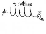
First of all, would this plan work? And secondly, I am just not sure how to get the power to all of the LED's. I plan on having about 10 of these loops, with an LED for each, and I just plain don't know how to daisy chain the power to each of the led's with this footswitch schematic, if it is possible at all. I assume that I would be able to run 10 LED's off of a 9v power source, but again, I really don't know.
Thank you for your time. If anyone has any suggestions for improvements, ideas, criticisms or whatever , I would really appreciate them.
-JM
I am planning on building my own pedal board, and I saw the true-bypass strip idea at http://www.pedalboards.com (scroll down a bit, it is there) and I would really like to build one of those to go onto the pedal board.
I am planning on including LED's for each bypass loop, and will probably end up using this plan for the actual switch wiring, except that instead of the input and output jacks shown on the board, they would go to the previous footswitch and next footswitch, respectively, and instead of the board input and output, they will go to 1/4" jacks for each of the individual bypass loops for each pedal. Oh, also, I will ditch the battery in there, and run it straight off of the DC jack.
First of all, would this plan work? And secondly, I am just not sure how to get the power to all of the LED's. I plan on having about 10 of these loops, with an LED for each, and I just plain don't know how to daisy chain the power to each of the led's with this footswitch schematic, if it is possible at all. I assume that I would be able to run 10 LED's off of a 9v power source, but again, I really don't know.
Thank you for your time. If anyone has any suggestions for improvements, ideas, criticisms or whatever
, I would really appreciate them.-JM
Last edited:
")
") And for LEDs, I like SuperBrights....but thats just me.
And for LEDs, I like SuperBrights....but thats just me.