I have a-3340s machine but don't have schematics. I only have a-2340sx schematics scans, you can d-load zipped file of them here:
http://www.mzentertainment.com/studio_workshop_technical_archive.html.
Just want to share a though.
It looks like all three trimpots of the record ampl. section together with associated capacitors and resitors "form" the load network for the Q302 stage of the amplifier. So I would guess, even though Monitor CAL pot adjustment only affects the output level in SOURCE setting, but if you change the resistance value of that potentiometer you may upset the levels over the other two pots: Record Meter and Record. I don't know how "dramatic" this would be, and, maybe even this happens, then only you would need to do after is to recalibrate the channel again from the start.
If I was facing this situation, and I could not find the exact value of the pot, then I would get the pot of closest value below the original and I would add a resitor in series with the pot to compensate for the difference. So, for example, if the original value is 33K, and I have 25K pot, then I'd add a resistor in series of the value closest to 8K that I can find.
Now, it's easy to say, but to actually practically to implement this (to fit on the board etc) can be pain in the neck.
So, this is just a though, and maybe you don't need to worry about all this. You can just replace the pot with what ever you get and see how it works out.
Drop a not after you've done this and how it worked out.
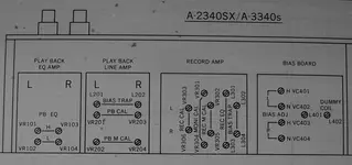
Attached Here is edited cut from simplified circuit of 2340sx, to illustrate what I was talking about. Also I am attaching scan of pots positions, just in case. I was not sure about which exactly pot did you break, as in 2340sx 33K pot is actually Record CAL pot, but it does not fit your description, (there must be some differences betweeen 2340sx and 3340s, but they are very similar machines).
 I completed the playback and monitoring part of calibration on the A-3340S, but just as I was finishing up the "minimum input level setting", where you calibrate the input monitor setting, I accidentally damaged one of the record amp card trimmers while adjusting the monitor level. The trimpot came apart and now, of course, passes no signal. So, channel 4 doesn't pass audio to the output in source setting, though the meter works fine and audio passes in tape setting. A parts designation would be helpful, as would a source for the part!

")