Tascam M-308B, M-312B, M-320B PARTS!

…it must’ve somehow been powerful enough that it killed the PT before the surge made it through to blow the fuses on the secondary side.
Fuses blow because the current flowing through them reaches a threshold where the filament heats up to the point of melting, which it does and as a result interrupts power. The current flows because of the demand of the devices downstream of the fuse, not the other way ‘round (for instance from a high voltage surge from upstream), so an event on the supply side of the power transformer wouldn’t necessarily blow the fuses.
I pulled the fuses out and had the power on for about 5 minutes. Nothing started smoking thankfully. I tested the secondaries again, this time on the transformer side of the fuse holders, and I wasn’t reading any voltage coming through. I had the power supply pcb unscrewed last time, and was testing the solder pads of the secondary leads instead. Don’t know why I was measuring a tiny bit of voltage last time vs now
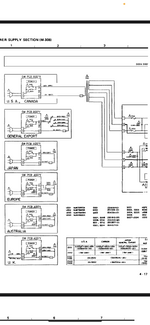
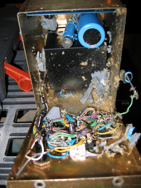
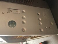
So how are you measuring for voltage? It’s going to be AC at the secondaries. Is your DMM set to AC volts? If not, set to AC, and on the secondary side you’ve got 6 colored wires right? This is from memory, but you’ll see two pairs of wires that are the same color…maybe two orange wires and two blue or purple wires? That I can’t remember…but you want to measure for AC volts across each colored pair of wires (like black probe on one orange wire and the red probe on the other orange wire…or whatever color the secondary wires are…and then do the same thing across the other same colored pair of secondary wires). I apologize if you know this already and that’s what you did…I’m just curious and want to make sure. It does indeed sound like your power transformer is zorched. I’ll go digging for the one I’m pretty sure I have here.
Assuming I have it and we strike a deal (I’m told I’m pretty reasonable…I’ll reach out to you directly if/when I find the transformer), what I recommend is that if you can, install it and then isolate the power supply PCB to test it before powering the whole console. I can’t recall if you can unplug the outputs of the power supply on an M-300…I’ll know the answer if I find the transformer because I also have I believe a complete power supply PCB assembly. But anyway if you can disconnect the outputs of the power supply, that will isolate the rest of the console from the power supply, so if there’s a problem with the PSU you can power it and let that tell you there’s a problem (smoke, stink, etc) without potentially damaging anything downstream. And you can measure with your DMM to verify the correct DC voltages at the outputs, and also measure for AC volts…should be at or very close to 0 AC volts at the DC outputs…like not more than a few mV AC. If you have an oscilloscope that would be even better to use to check. Anyway, I’m kind of getting ahead of things since I’ve still got to go hunting for the iron.

Stay tuned.
 
First of all, I am definitely a beginner in electronics, so thank you so so much for taking the time to help and educate me. Every repair project I do I am learning so much. I did have the dmm on ac, but was measuring each secondary wire separately to chassis ground. I just did it the correct way, between the negative and positive pairs of secondary wires, and I’m still getting 0v though.

I wonder in what way the PT is broken. I’m getting around 120v ac on the positive primary, and 0v on the neutral.

There is a symbol on the neutral wire just before the xformer on the schematic that is close to the iec symbol for a fuse, but with rounded edges. Could it be an internal fuse in the PT? Maybe that is what is blown? The transformer also doesn’t actually look burned at all…

Thanks again Sweetbeats! School me, please!
 

Attachments

  • 090E3CEE-B641-4B99-9632-810CDA476403.png
    090E3CEE-B641-4B99-9632-810CDA476403.png
    829.8 KB · Views: 6
Last edited:
First of all, I am definitely a beginner in electronics, so thank you so so much for taking the time to help and educate me. Every repair project I do I am learning so much. I did have the ddm on ac, but was measuring each secondary wire separately to chassis ground. I just did it the correct way, between the negative and positive pairs of secondary wires, and I’m still getting 0v though.

I wonder in what way the PT is broken. I’m getting around 120v ac on the positive primary, and 0v on the neutral.

There is a symbol on the neutral wire just before the xformer on the schematic that is close to the iec symbol for a fuse, but with rounded edges. Could it be an internal fuse in the PT? Maybe that is what is blown? The transformer also doesn’t look burned at all…

Thanks again Sweetbeats! School me, please!
I had to reach out to people much smarter than me because, for all the times I’ve referenced the M-300 power supply schematic, I’ve never noticed that component. But I didn’t know the answer, so I reached out to a group I’m part of and a friend who I’ll call Thomas…because his name is Thomas…indicated it is likely a “fusible link that is embedded in the transformer package.” Gold star for you and your pops.

When you mentioned measuring 120VAC on the transformer hot primary wire, and 0VAC on the neutral primary wire, was that referenced to the building ground or chassis ground or what? If you measure AC volts across the hot wire and ground of the AC line it should read, in the US, around 120VAC. And if you measure for AC volts across the neutral wire and ground it will, or SHOULD be 0V. Dead zero. That’s because they both reference “earth”. The ground wire in a three prong outlet is a safety ground. It does nothing unless the neutral fails. It is a backup for the neutral wire. It gives another path for power to cycle if the neutral wire fails instead of through you. So there should be no voltage differential between ground and neutral. I think your power input to the transformer primary is fine from the power outlet, but you know what I’m going to say next…the fusible link has likely failed, and maybe it failed secondary to an event that also damaged the primary coil windings before the link failed. So even though the link on the neutral primary coil wire is hypothetically roached, there may be leakage across coil windings to the chassis or to the neutral wire anyway in spite of the open link. My hunch is if you left it switched on for long enough it would get stupid, stupid hot, because it is now basically a heating coil and the failure would accelerate as it continued to heat, and then eventually it would (hopefully) trip the circuit breaker in your service panel before catching fire.

I think I’ll go look for a transformer.

By the way I also have learned the vast majority of what I know about this sort of stuff from trying to fix things and having people help me and reading…and also making mistakes and breaking stuff…making electronic stink…I never knew an exploded electrolytic cap would make a room smell like fish…like…forever…and you can make them explode by installing them backwards…by mistake…even though you triple-checked the install…and they don’t blow up right away all the time. Sometimes it takes hours and hours and then you find out they can sound *just* like a Glock 45 going off and make you piss yourself a little. And the innards go EVERYWHERE. And a decade later, even after hosing the entire power supply chassis down with iso alcohol and other cleaners you can still kind of smell it. Maybe it’s just some PTSD. But this is an example of the fun things you too can learn when you’re an electronics hobbyist.

IMG_0193_1_1.JPG
 
Last edited:
Gotcha…

9CD66B67-3426-4CD9-8DA0-4260BBEACEE4.jpeg

Here’s the trick though…it’s for an M-312B…I know I parted out my first M-300 series console, an M-308B…I remember now hacking out the power transformer from the spaghetti guts to load test it and see if it would work for another project I was working on. It didn’t. And I also recall pulling the 7805 regulator off the power supply PCB to repair something else in a pinch. But I can’t find either of those now…I’m thinking it’s possible I sold them. But I did find my box of some-assembly-required M-312B that I parted out and still have most of it because there’s a pot on each input PCB I eventually want to transplant into my 80s prototype Tascam console…and the entire power supply array is there from the power switch all the way through the power supply PCB and phantom supply. The problem is I’m not sure if the transformer is a drop-in for an M-308, because the M-312B transformer has the taps for the phantom supply as well as the BNC lighting jack…the taps for the +/-15V rails and the rails that power the headphone amp (not sure what those are regulated to and the schematic doesn’t show this…grr) should be the same so you’re good there, it’s just whether or not the additional taps required additional windings and a larger transformer chassis. I suspect not. But this is what I need you to do, post a pic of your transformer so I can visually compare, and also measure and post the outside dimensions of it, as well as the hole spacing of the mounting screws, and I can then compare to mine and see if it will bolt up, if you’re even still interested since it’s not straight M-308. If it’s the same size and hole pattern it is literally then essentially the same transformer with the added bonus of having AC taps for lighting and taps for a phantom supply. Let me know.
 
Gotcha…

View attachment 122930

Here’s the trick though…it’s for an M-312B…I know I parted out my first M-300 series console, an M-308B…I remember now hacking out the power transformer from the spaghetti guts to load test it and see if it would work for another project I was working on. It didn’t. And I also recall pulling the 7805 regulator off the power supply PCB to repair something else in a pinch. But I can’t find either of those now…I’m thinking it’s possible I sold them. But I did find my box of some-assembly-required M-312B that I parted out and still have most of it because there’s a pot on each input PCB I eventually want to transplant into my 80s prototype Tascam console…and the entire power supply array is there from the power switch all the way through the power supply PCB and phantom supply. The problem is I’m not sure if the transformer is a drop-in for an M-308, because the M-312B transformer has the taps for the phantom supply as well as the BNC lighting jack…the taps for the +/-15V rails and the rails that power the headphone amp (not sure what those are regulated to and the schematic doesn’t show this…grr) should be the same so you’re good there, it’s just whether or not the additional taps required additional windings and a larger transformer chassis. I suspect not. But this is what I need you to do, post a pic of your transformer so I can visually compare, and also measure and post the outside dimensions of it, as well as the hole spacing of the mounting screws, and I can then compare to mine and see if it will bolt up, if you’re even still interested since it’s not straight M-308. If it’s the same size and hole pattern it is literally then essentially the same transformer with the added bonus of having AC taps for lighting and taps for a phantom supply. Let me know.

Wow, wow, wow! You’re an absolute fricken angel Sweetbeats! …And Thomas!

Luckily I haven’t blown any caps on my projects yet. Very luckily apparently haha!

And to answer your last question, I was measuring the primaries separately to chassis ground. Is that kosher?

Maybe after I get that replacement xformer I’ll try some surgery on the dead one and see if that fuse is accessible.

I’m stoked that this info is all accessible for anyone out there who might eventually run into this rare issue as well, so cool

Ooo, 80’s prototype Tascam console… sounds intriguing!

I will take those measurements and photos now. And I’m definitely still interested even though it’s not the m-308 tranny, I’ve scoured the web looking for one and come up with nada. Thanks a million man! 🙏
 
Last edited:
Ok here we go:

PT is
2 5/8” wide x 2 3/8” tall x 2 3/4” deep (from my perspective with mixer sitting on back)

Mount holes are 3/4” apart x axis (with mixer sitting on back, as pictured) and 2 3/4” apart y axis!

Looks like there’s some alternate unthreaded mount holes too, I could use nuts with those if they line up with the B transformer.

Those mount holes are 2 15/16” apart x, 2 3/4” apart y.

Cheers!
 

Attachments

  • B026BD2F-C307-488E-84AE-0A0C9FB12C38.jpeg
    B026BD2F-C307-488E-84AE-0A0C9FB12C38.jpeg
    3.4 MB · Views: 5
  • 420C8689-A185-4EDC-8C09-6EC6C5A309EA.jpeg
    420C8689-A185-4EDC-8C09-6EC6C5A309EA.jpeg
    3.5 MB · Views: 5
  • 8A7A0244-1B82-4D29-9F6A-BB2DD04ED014.jpeg
    8A7A0244-1B82-4D29-9F6A-BB2DD04ED014.jpeg
    2.4 MB · Views: 5
I was measuring the primaries separately to chassis ground. Is that kosher?

You should measure across the hot and neutral wires in an AC circuit. Sure you *can* measure from each wire to the chassis, but here is the problem with that in this scenario: Is your power cable stock and just two prong? If so the chassis ground is floating from the building ground. There’s no bonded reference to the “earth” that the neutral wire references. So it all depends on how they did or didn’t ground the chassis, and how the neutral wire interfaces the ground scheme of the device…remember AC power is Alternating Current, not Direct Current as with DC power. With DC power you have linear current flow from a point of high voltage potential (the positive side) to a point of low voltage potential (the negative or “ground” side). Think of water flowing over a water wheel making it turn. The wheel can then do work. This is analogous to DC power, where the water is the flow of current in a linear path and the water wheel represents a DC motor, though instead of water and paddles on the wheel you have electrons and coil windings and magnets. With AC you have current alternating cyclically in a positive phase and then a negative phase over and over…back and forth…push, pull, in a sine wave. So with AC power you have not only voltage and current to consider, but also frequency…the rate of the pushing and pulling. In the US that rate or frequency is 60 cycles or hertz. Think of the connecting rod in an internal combustion engine, or on the drive wheels of a steam locomotive…the rod is going up and down (or back and forth) making the crankshaft or drive wheel rotate. This is like AC power driving an AC motor. So when measuring DC voltage you have to measure between the positive side and the negative side (or “ground”) to measure the differential or *difference* between the high potential (positive) and the low potential (negative)…that’s what we are measuring with DC voltage, the difference between the positive and the negative or ground reference. With AC voltage we are measuring the amplitude or “height” above and “depth” below the center 0V reference of the sine wave…think of the stroke of the connecting rod…the length of the travel up and down in total is what we are measuring with AC volts, because the rod does work in both directions. There are a couple different ways we measure it, but we don’t need to get into that here. So you want to measure between the line and the neutral wires. You certainly could measure to “ground” because, remember in my previous post I indicated the ground socket of a grounded outlet *should* be tied to the same ground reference as the neutral wire in the service panel, because the ground is just a safety backup in case the neutral wire fails, but before you use the ground as your reference for the hot wire you have to verify the ground socket is actually bussed to the same reference as the neutral wire in the service panel, then verify the ground in the outlet propagates to the chassis of the device (typically via a three prong power cord), and that the ground wire in the power cord then positively bonds to the chassis of the device. If you don’t know those things, then you can’t rule out that there may be a voltage differential between the device chassis and the building ground because the chassis ground is “floating” (i.e. not referenced or “bonded” or connected to the building ground), and then if you reference the line wire or “hot” wire to the floating chassis the voltage reading will be the sum of the line voltage and the ground differential. This differential is typically pretty small, but, hey, if you have the neutral wire right there, which is the primary reciprocal path for the current in the hot wire, why not just measure across that and the hot? Hopefully that makes some sense. I know that’s a fair amount of detail, but you seem to have a pretty decent grasp of things so there you go.

Maybe after I get that replacement xformer I’ll try some surgery on the dead one and see if that fuse is accessible.

It may be accessible, but it’s not likely a “fuse” per se, or some kind of replaceable component, it’s likely an embedded expendable link that when used is done. And beyond that if the link is wasted and you are still smelling hot electrical smell, the transformer is further damaged. A broken fusible link should cut all power from the primary coil of the transformer because when expended it breaks that reciprocal neutral path back to the power station for the hot wire. If it’s getting hot that means current is still flowing where it shouldn’t be, which suggests irreparable damage. But of course you’re always welcome to tear the thing open to look at the guts. I might do the same thing just out of curiosity, but my hunch is that is the only purpose that will serve; to satisfy curiosity. I think it’s most likely the transformer is irreparable.

Ooo, 80’s prototype Tascam console… sounds intriguing!

It’s this one in this big thread:
https://homerecording.com/bbs/threads/tascam-m-___-story.270992/

So regarding the M-312B power transformer, your pic showing the side panel does remind me it looks like it is fabbed to mount multiple transformer assemblies depending on if it is an M-308, M-312 or M-320, and indeed it looks like the fastener spacing on my transformer is 2 15/16” x 2 3/4”! See pics below. Note the end of the measuring tape is on the 1” mark for better measuring accuracy, so subtract 1” from the result you see to the right end of the tape in the pictures:

6436F7B5-1093-41EE-B811-F8CFD0F2C45F.jpeg

C94C6EE2-CE77-46B5-A907-9477047D14ED.jpeg

And as far as the dimensions of the assembly itself, my hunch is it will fit by virtue of the fact there are corresponding mounting holes on your chassis, but the height, width and depth of the assembly, if we consider the mounting surface of the assembly as the “bottom” is approximately 2 3/4”H x 3 11/16”W x 3 3/8”D. Here are pictures:

2AB2B6CB-AF26-4BBF-88E3-27B629A7CE5E.jpeg

78B6E04C-DEEF-4ADD-AF48-8F42640D9766.jpeg

122FB844-F9FC-42B7-A393-8079EB65FC1B.jpeg
 
You should measure across the hot and neutral wires in an AC circuit. Sure you *can* measure from each wire to the chassis, but here is the problem with that in this scenario: Is your power cable stock and just two prong? If so the chassis ground is floating from the building ground. There’s no bonded reference to the “earth” that the neutral wire references. So it all depends on how they did or didn’t ground the chassis, and how the neutral wire interfaces the ground scheme of the device…remember AC power is Alternating Current, not Direct Current as with DC power. With DC power you have linear current flow from a point of high voltage potential (the positive side) to a point of low voltage potential (the negative or “ground” side). Think of water flowing over a water wheel making it turn. The wheel can then do work. This is analogous to DC power, where the water is the flow of current in a linear path and the water wheel represents a DC motor, though instead of water and paddles on the wheel you have electrons and coil windings and magnets. With AC you have current alternating cyclically in a positive phase and then a negative phase over and over…back and forth…push, pull, in a sine wave. So with AC power you have not only voltage and current to consider, but also frequency…the rate of the pushing and pulling. In the US that rate or frequency is 60 cycles or hertz. Think of the connecting rod in an internal combustion engine, or on the drive wheels of a steam locomotive…the rod is going up and down (or back and forth) making the crankshaft or drive wheel rotate. This is like AC power driving an AC motor. So when measuring DC voltage you have to measure between the positive side and the negative side (or “ground”) to measure the differential or *difference* between the high potential (positive) and the low potential (negative)…that’s what we are measuring with DC voltage, the difference between the positive and the negative or ground reference. With AC voltage we are measuring the amplitude or “height” above and “depth” below the center 0V reference of the sine wave…think of the stroke of the connecting rod…the length of the travel up and down in total is what we are measuring with AC volts, because the rod does work in both directions. There are a couple different ways we measure it, but we don’t need to get into that here. So you want to measure between the line and the neutral wires. You certainly could measure to “ground” because, remember in my previous post I indicated the ground socket of a grounded outlet *should* be tied to the same ground reference as the neutral wire in the service panel, because the ground is just a safety backup in case the neutral wire fails, but before you use the ground as your reference for the hot wire you have to verify the ground socket is actually bussed to the same reference as the neutral wire in the service panel, then verify the ground in the outlet propagates to the chassis of the device (typically via a three prong power cord), and that the ground wire in the power cord then positively bonds to the chassis of the device. If you don’t know those things, then you can’t rule out that there may be a voltage differential between the device chassis and the building ground because the chassis ground is “floating” (i.e. not referenced or “bonded” or connected to the building ground), and then if you reference the line wire or “hot” wire to the floating chassis the voltage reading will be the sum of the line voltage and the ground differential. This differential is typically pretty small, but, hey, if you have the neutral wire right there, which is the primary reciprocal path for the current in the hot wire, why not just measure across that and the hot? Hopefully that makes some sense. I know that’s a fair amount of detail, but you seem to have a pretty decent grasp of things so there you go.


It may be accessible, but it’s not likely a “fuse” per se, or some kind of replaceable component, it’s likely an embedded expendable link that when used is done. And beyond that if the link is wasted and you are still smelling hot electrical smell, the transformer is further damaged. A broken fusible link should cut all power from the primary coil of the transformer because when expended it breaks that reciprocal neutral path back to the power station for the hot wire. If it’s getting hot that means current is still flowing where it shouldn’t be, which suggests irreparable damage. But of course you’re always welcome to tear the thing open to look at the guts. I might do the same thing just out of curiosity, but my hunch is that is the only purpose that will serve; to satisfy curiosity. I think it’s most likely the transformer is irreparable.


It’s this one in this big thread:
https://homerecording.com/bbs/threads/tascam-m-___-story.270992/

So regarding the M-312B power transformer, your pic showing the side panel does remind me it looks like it is fabbed to mount multiple transformer assemblies depending on if it is an M-308, M-312 or M-320, and indeed it looks like the fastener spacing on my transformer is 2 15/16” x 2 3/4”! See pics below. Note the end of the measuring tape is on the 1” mark for better measuring accuracy, so subtract 1” from the result you see to the right end of the tape in the pictures:

View attachment 122951

View attachment 122954

And as far as the dimensions of the assembly itself, my hunch is it will fit by virtue of the fact there are corresponding mounting holes on your chassis, but the height, width and depth of the assembly, if we consider the mounting surface of the assembly as the “bottom” is approximately 2 3/4”H x 3 11/16”W x 3 3/8”D. Here are pictures:

View attachment 122957

View attachment 122963

View attachment 122966

Very informative, that makes sense. Thanks a lot! I’ve been working mostly on dc circuits thus far if you hadn’t noticed, haha

Great! Well I measured those dimensions inside the chassis to be safe, and it’ll fit!

I know I wouldn’t be using the PT to its full potential with it’s extra secondaries, but if you’re still comfortable having it go to an M-308, I’m totally down!

Send me an email and let’s arrange everything! Thanks so much man!!

It’s Nate_sk8_8 (at) Hotmail.com :)
 
Last edited:
There is a symbol on the neutral wire just before the xformer on the schematic that is close to the iec symbol for a fuse, but with rounded edges. Could it be an internal fuse in the PT? Maybe that is what is blown? The transformer also doesn’t actually look burned at all…

Thanks again Sweetbeats! School me, please!
Years ago, It was somewhat common for the Peripheral Expansion Box for a TI99/4a computer to die suddenly. It often happened when people were trying to mod the system to add extras like a pair of floppy drives. It turned out that there was a fuse inside the plastic casing around the transformer. The solution was to break away the plastic, and mount a fuse in a holder. This allowed easy replacement if the fuse popped.
 
Been a while but if you have any channel cards
I'm parting out a Tascam M-308B. Rouh on the outside, super clean on the inside. Many of the parts are completely compatible with the non-'B' series 300 mixers.

It goes like this:

  1. PM me
  2. Tell me what you need
  3. I'll tell you if I have it
  4. You make me an offer
  5. We come to terms so I can get the thing off my workbench

:)

IMG_9166_2_1.JPG


Oblique%20(no%20flash).JPG
Been a while but if you still have any channel cards and faders I’m very interested! My email is jerryulichny@gmail.com
 
Gotcha…

View attachment 122930

Here’s the trick though…it’s for an M-312B…I know I parted out my first M-300 series console, an M-308B…I remember now hacking out the power transformer from the spaghetti guts to load test it and see if it would work for another project I was working on. It didn’t. And I also recall pulling the 7805 regulator off the power supply PCB to repair something else in a pinch. But I can’t find either of those now…I’m thinking it’s possible I sold them. But I did find my box of some-assembly-required M-312B that I parted out and still have most of it because there’s a pot on each input PCB I eventually want to transplant into my 80s prototype Tascam console…and the entire power supply array is there from the power switch all the way through the power supply PCB and phantom supply. The problem is I’m not sure if the transformer is a drop-in for an M-308, because the M-312B transformer has the taps for the phantom supply as well as the BNC lighting jack…the taps for the +/-15V rails and the rails that power the headphone amp (not sure what those are regulated to and the schematic doesn’t show this…grr) should be the same so you’re good there, it’s just whether or not the additional taps required additional windings and a larger transformer chassis. I suspect not. But this is what I need you to do, post a pic of your transformer so I can visually compare, and also measure and post the outside dimensions of it, as well as the hole spacing of the mounting screws, and I can then compare to mine and see if it will bolt up, if you’re even still interested since it’s not straight M-308. If it’s the same size and hole pattern it is literally then essentially the same transformer with the added bonus of having AC taps for lighting and taps for a phantom supply. Let me knowSweetBeats!
Gotcha…

View attachment 122930

Here’s the trick though…it’s for an M-312B…I know I parted out my first M-300 series console, an M-308B…I remember now hacking out the power transformer from the spaghetti guts to load test it and see if it would work for another project I was working on. It didn’t. And I also recall pulling the 7805 regulator off the power supply PCB to repair something else in a pinch. But I can’t find either of those now…I’m thinking it’s possible I sold them. But I did find my box of some-assembly-required M-312B that I parted out and still have most of it because there’s a pot on each input PCB I eventually want to transplant into my 80s prototype Tascam console…and the entire power supply array is there from the power switch all the way through the power supply PCB and phantom supply. The problem is I’m not sure if the transformer is a drop-in for an M-308, because the M-312B transformer has the taps for the phantom supply as well as the BNC lighting jack…the taps for the +/-15V rails and the rails that power the headphone amp (not sure what those are regulated to and the schematic doesn’t show this…grr) should be the same so you’re good there, it’s just whether or not the additional taps required additional windings and a larger transformer chassis. I suspect not. But this is what I need you to do, post a pic of your transformer so I can visually compare, and also measure and post the outside dimensions of it, as well as the hole spacing of the mounting screws, and I can then compare to mine and see if it will bolt up, if you’re even still interested since it’s not straight M-308. If it’s the same size and hole pattern it is literally then essentially the same transformer with the added bonus of having AC taps for lighting and taps for a phantom supply. Let me know.
Hey SweetBeats! I’m looking for M312b female XLR locking jacks if they’re still available. Let me know! Much thanks in advance.

TDiaz0262 at gmail . Com is where you can reach me.
 
Back
Top