sweetbeats
Reel deep thoughts...
You both could start new threads.
")
hi,Hi.
So I don’t know what the ideal bias level is for LPR90. It will be different than LPR35, and if it was me I’d be using the LPR35…not because of the bias issue. One of the things that’s problematic or finicky about a 388 is since the R/P heads don’t have edge slots (narrow slots cut above track 8 and below track 1), as a wear path is established, the edges of the tape can curl at the top or bottom of the wear path. And by “curl” I mean ever so slightly lift. This is greatly exacerbated if the wear path was established by the factory specified Ampex/Quantegy 457. Ampex/Quantegy tape slitting equipment was not as precise as pretty much every other tape manufacturer at the time. The tape slitting accuracy was, IIRC, 0.001~0.003” off of the specified tape width. To avoid tape being slightly too wide and causing problems they slightly undersized the width. Again we’re talking a couple thousands of an inch. But what results then with a tape path established by Ampex/Quantegy tape, when you run properly slitted tape, it is slightly too wide in the path…usually one edge curls or slightly lifts. On a super narrow format machine like a 388 the result is signal and fidelity loss on track 1 or track 8, and also issues with edge shed getting on the head. It takes almost nothing as far as debris or edge lift to cause, at times, almost complete loss of signal during record or playback. If there are edge slots that eliminates the sides of the wear trough and now slight variations in tape width don’t matter. Edge shed can still be a problem though at other points in the tape path. The thicker more stiff LPR90 will exacerbate this condition if this is at least part of what you are dealing with. The solution is a relap, unless the wear path is slight. In that case sometimes you can fast-wind through a reel of tape a couple times with the lifters defeated to try and abate the edge lift…try and wear down the path at the edges.
Regarding the bias, again, I don’t know what the bias requirement is for LPR90, you’ll have to determine that by going through the painful process I did, or just take a stab at it. It sounds though like an overbias condition you have there though. With too little bias the distortion level is too high, and as you crest the sweet spot with the bias level the HF performance drops.
When you said you adjusted the azimuth and head “tilt” what did you mean? Usually that’s a euphemism for zenith, but the zenith is fixed on a 388. So did you adjust the wrap angle? I would never, ever do this on a machine with an already-established wear path, because if you change the wrap angle the tape can no longer properly contact the face of the head, even if it was off originally…you’ll go from non-ideal to worse. If what I’m saying doesn’t make sense I’m happy to explain it in other terms. But this goes for rotating fixed guides too. You never ever do that unless it is at the time of a relap and optical setup of the heads and guides in the headblock assembly.
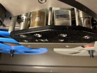
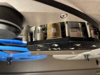
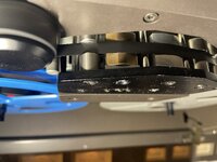
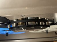
So I know I’m not necessarily a ray of sunshine here, but let me know what follow-up questions you have and maybe try and post some pictures of your R/P head and tape path.
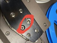
So yes, to be a little more clear, we did follow the procedure in the manual to adjust the TANGENCY adjustment screws. Sorry about the "tilt" term which is actually not the proper term. As the manual says:
"Slightly loosen the mounting screws which hold record/reproduce head in place and adjust the tangency using adjustment screw,
for maximum output. When the maximum output is attained, retighten both mounting screws."
Thats what we did.
Now, for the use of LPR 90, I leave a link here with the specs of the tape:
https://static1.squarespace.com/sta...598576/1660032190137/fiche_lpr90_rtm_2022.pdf
Maybe you would be better suited than me to find out if it matches ampex / quantegy tape from back then.
Many people told me that LPR 90 worked just fine with tascam 388, thst it was basically the exact same thing than LPR35 but only a little more robust…
…but then you adressed a very interesting issue regarding edge shed getting on the head. Maybe it’s the problem. I would leave a video of how the vu meter of channel 1 behaves when played a 400 hrtz frequency from my nagravox calibration tape but the website doesnt take videos. It basically bounces from one side to the other with fluctuations around -1 and +1 dbs
There is also a distinct sound to it. A little crackling, like the channel is "choking" on something. It’s not extremely audible or problematic, but it’s just there.
Hey!So here’s what I would do…P105 is not your problem. It connects only to the BUSS IN jacks. P102, however, is the connector that provides logic and audio power to the BUSS B PCB as well as ground and the AUX and EFF signal. If there is a problem with faulty connections or solder joints there you could have issues with intermittent audio and other odd switching issues because the logic power is there, and there is a logic chip on the BUSS B PCB that manages automatic source switching involving the stereo buss. You say you “scavenged” the board for bad solder joints but you’re not going to be able to tell by looking, even under magnification. If you have little sparks with manipulation at P102 on pin 1, that’s the +5V power rail. It shouldn’t be doing that. Ever. So if it was me I’d start by reflowing the solder joints both on the M BUSS PCB and on the BUSS B PCB associated with P102. Do that and then report back what issues remain.
Hi!When you say you “can’t get any sound”, be specific as to where there is no sound.
I’m assuming you mean no sound when monitoring the STEREO buss, correct? Is this true at the STEREO OUT jacks as well as in the headphones when the monitor select switch above the headphones level knob is set to STEREO?
Do the STEREO meters function when you set them to monitor the AUX and EFF busses?
What happens if you connect a source to the STEREO BUSS IN jacks? Is there activity on the STEREO meters and signal at the STEREO OUT jacks or in the headphones when the monitor source is set to STEREO? Try this test both with one or more L-R assign switches latched or in the down position on one or more input channels, and also with all L-R assign switches in the unlatched or up position.
What we are doing here is, using the Block Diagram and the 388’s own features and functions, learning as much as we can about where the problem originates before we drill down to the schematic level or do any tracing of the problem. I’m not surprised your repair of the solder joints didn’t fix everything, but good job tackling part of the issue. The description of the problem(s) sounded like compound issues to me, and I have a hunch I know what the problem is, but if you can execute the above tests and answer the questions it will help.