Tascam 388 Story...

I'll probably do some schematic back-tracking to test it (since I don't have a schematic for the RC-71, but schematics from any unit that uses the RC-71 will tell me what I need to know and I have schematics for the 48, 234 and 388.)
here's diagram I've drawn when was figuring it out as I was making up "RC-71" using the control buttons/board from teac 144: link to diagram: http://www.mzentertainment.com/pics/tascam_rc_71/dr_zee_workshop_tascam_rc_71_schematics.gif,
more details here: http://www.mzentertainment.com/studio_workshop_tascam_rc_71.html
the thing is though, I never had actual rc-71 unit, but I can tell that what's on that diargam works fine :D (tested with tascam 32)

Cory, is there anything else inside the box besides buttons and leds ?
 
RC-71 Tear-Down

ZEE...looks like the circuit board is really straight-forward...no other components on the board except for some current limiting 470ohm resistors for the LED's.

4 screws and the cover comes off:

IMG_1649_1_1.JPG


4 more little screws on the top of the switch panel and two screws on the bottom and you can kind of separate the thing...the LED's appear to be soldered after the PCB and everything is together so the switch panel is stuck to the PCB unless you want to desolder...I don't wanna.

IMG_1650_2_1.JPG


Here's the trace side of the PCB...straight-forward...and in the last picture I'm pointing to the location of those resistors:

IMG_1651_3_1.JPG


IMG_1652_4_1.JPG
 
Uh, cool! Thanks a bunch for dissecting it :)
I guess I better add resistors to the diagram with a note. In my case it seems to work ok without them, but also I guess this would depend on leds a DIYer uses .... ok, it's no big deal really.
One thing I don't get here is, that it does not look like the numbers on the Board correspond with pins numbers of the connector... :confused: :confused: , or maybe I completely miss something here.
Also looks like there's "space" there reserved for another control button and another led.... what could that be? .... some "future possible feature" or something ? :)
 
Yeah, I wondered about the third switch and LED pads (as well as the third pad for each switch...?) Anyway, all mysteries were put to bed when I saw the tiny lettering "EJECTOR SEAT" on the PCB...for bad talent? kidding

And the resistors for the LED's...haven' looked at all but I'd assume the rmote is functioning on a 5 ~ 6V rail? Some LED's can handle that right?

And you're right...terminal number on circuitboard does not correspond to connector pin number with the exception of pins 5 and 7.

PCB/connector
1/4
2/1
3/2
4/8
5/5
6/3
7/7
8/6
9/12
10/9
11/10
12/11
 
..I'd assume the rmote is functioning on a 5 ~ 6V rail?
I'd assume not , well, not the way you put it in respect to "LED's issue" :)
you actually need to look into schematics if you care to know for sure (I didn't ... :o:p). The supply V+ may be 5V or what ever there for the control circuit/(s) and associated ICs, but this does not mean that the actual "Supply voltage" for the LEDs is the same as Supply voltage for the circuit(s). I'd hate to guess, as I have not looked into how exactly things are there, but the LEDs must be in some switching transistors circuits.
I'd guess if you measure voltage between Pin 11 of the connector and the ground, you may actually have 5V (or what ever control circuit supply is), but it would not be the same between Pin 11 and 10/12.

... 5 ~ 6V ...? Some LED's can handle that right?
Well, afaik, to do it "right" you'd need to arm the LED (meaning to set REC or Pause on the machine), and while in that state, measure the actual "supply voltage" for the led with DVM btween pin 11 and 10(pause) / 12(rec). Pin 11 must be positive. Now you know the actual LED supply voltage, let's call it V(LS).
Let's imagin that you get V(LS)=3Volts
Now you need to know the caracteristic of the LEDs you want to use, which are Forward Current and Forward Voltage. If you don't know for sure you can sort of find out by experiment with adjustable DC supply and ammeter in series, adjusting voltage slowly to the point when the LED is nicely bright, but not too bright and is not burning :D.
So lets' say led's forward current I(led)=20mA and forward voltage is V(led)=2Volts.
Now you can calculate the value of current limiting resistor R(L) for the given LED with given "Supply Voltage":
R(L)=V(LS)-V(led)/I(led)
so
R(L)=3Volts-2Volts/0.02A=50 Ohms
***********
here's on line calculator :) - http://led.linear1.org/1led.wiz , this is cool, as it actually "reccomend" an actual resistor value/wattage, not just "math value".
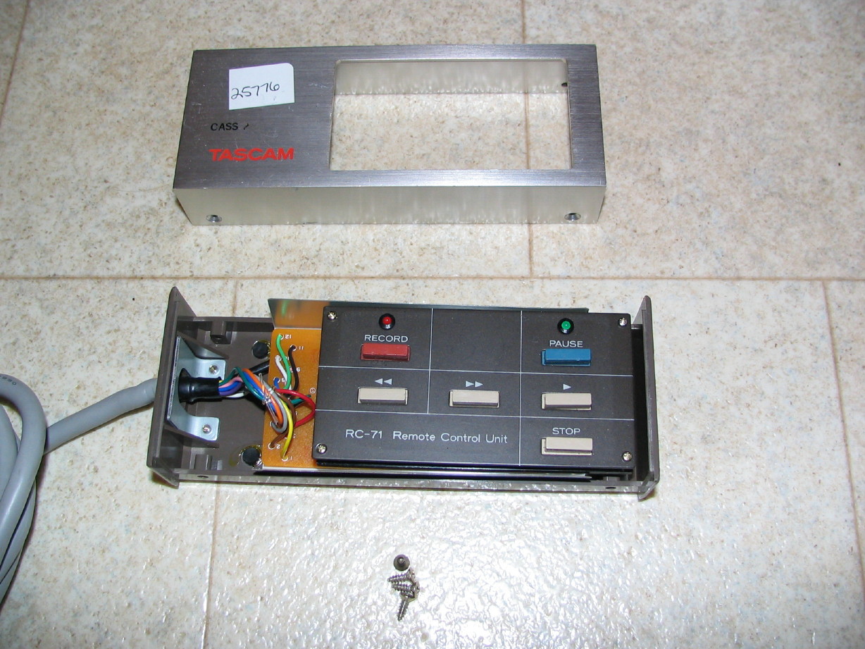
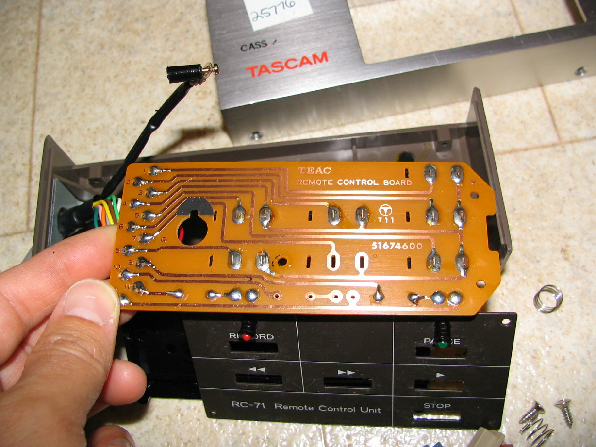
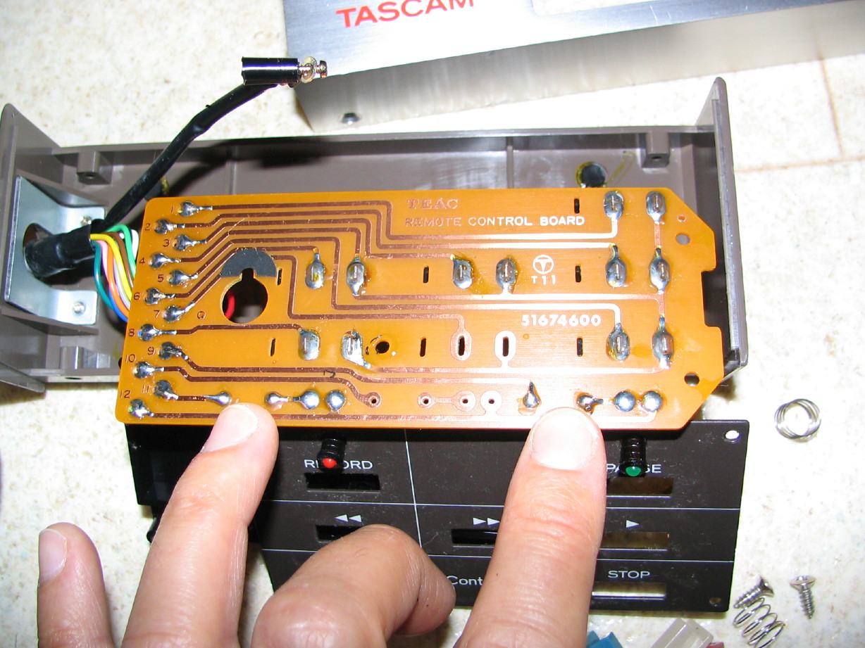
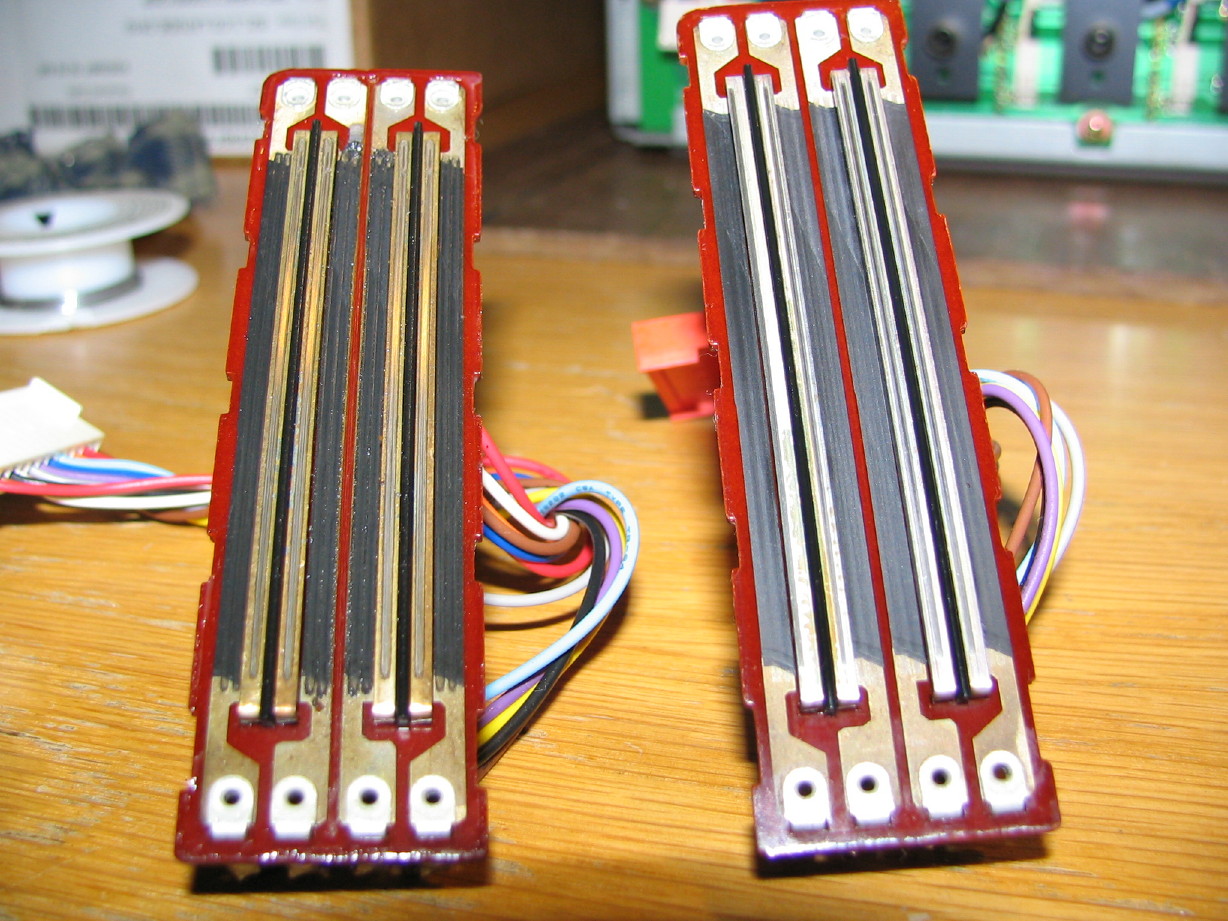
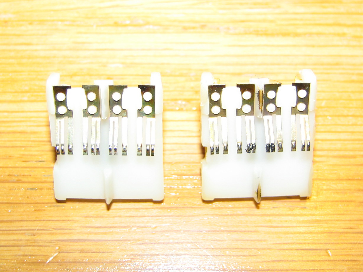
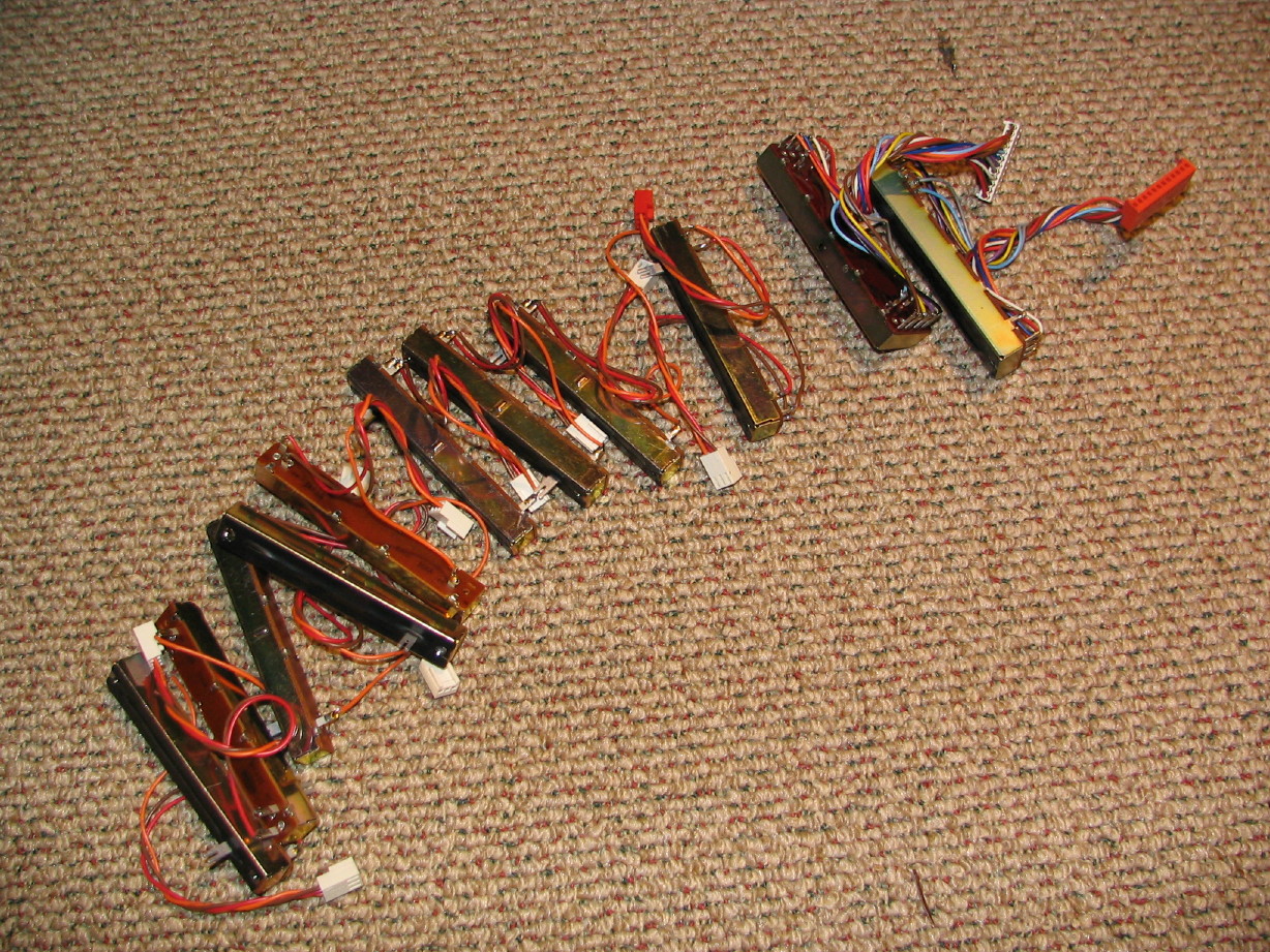

PCB/connector
1/4
2/1
3/2
4/8
5/5
6/3
7/7
8/6
9/12
10/9
11/10
12/11

That looks all correct.
Approved by special federal agency - ME! :p :p :p heh heh
:D

**********
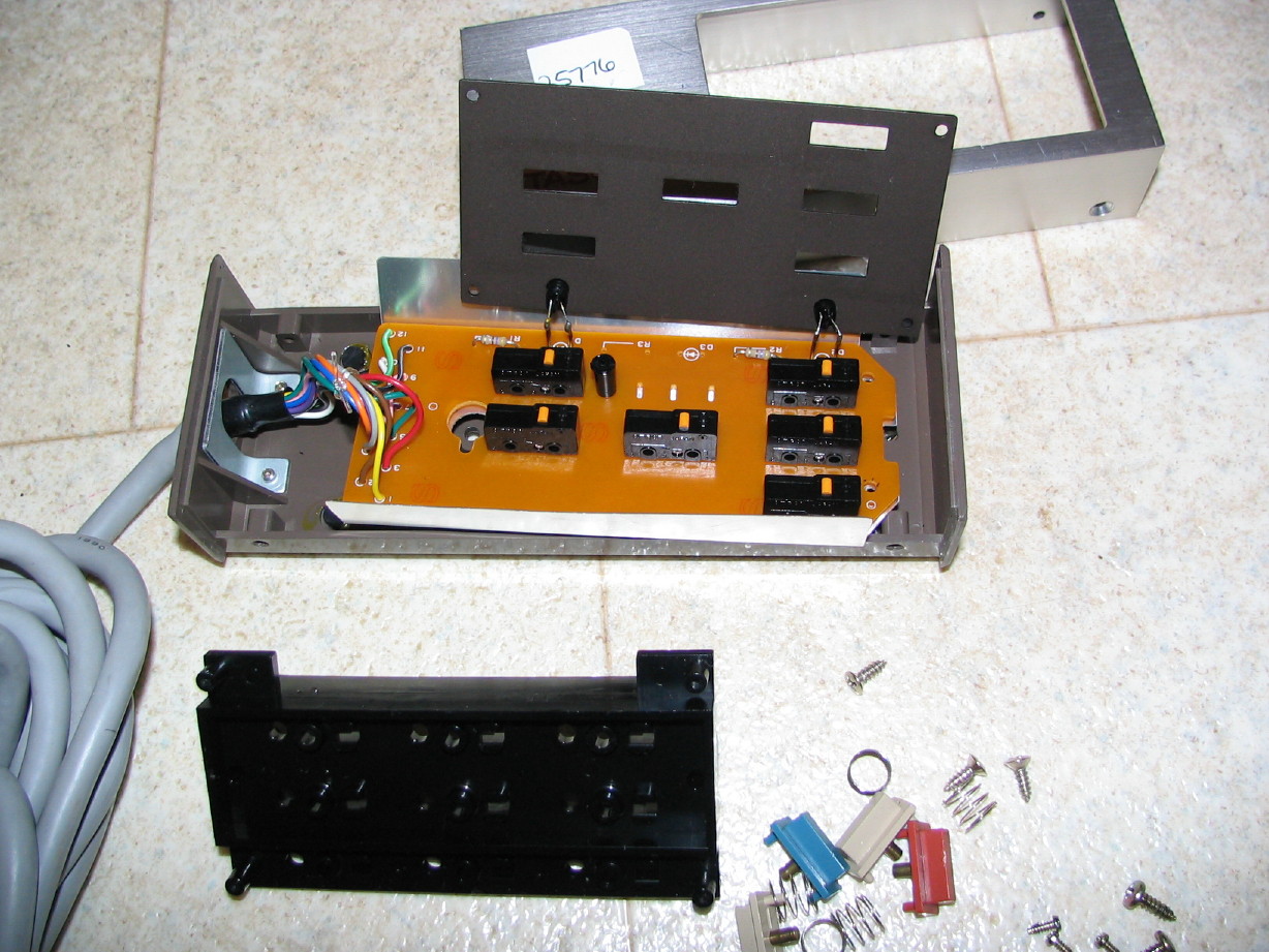
extra button - how about Punch IN/OUT feature on the remote ? :)
 
Cool calculator federal guy...thanks!!!

My tax dollars at work. :D

ooooo...punch in/out on the remote...that'd be neat...not sure how to punch the button plate for the extra button, or where to get the extra button, but the rest would be pretty easy assuming it is a momentary switch function and those two pins aren't used...
 
last night I wasted my time. Measured the voltage on tascam 32 between pins 11 and 10/12. So when LEDs are "ON" I get WOW! - 25 Volts DC there :eek: ... heh heh, then I'm thinking to myself: "hmmmmmmmmm, that's interesting. How so????". So I 've tried inserting 1K resistor and 500 Ohms resistor, and - no difference, same "result", the remot's LED is the same - nice and bright. So I've "guessed-concluded" to myself, that there must be constant current LED driver circuit or IC of a sort inside (?????). I don't feel like opening up the machine to investigate, don't have 32's schematics either.
So? well, it is what it is.
I've added 470R (s) to the diagram just in case. Other machines may have different internal LED drivers design , I have no clue, really.
:(
 
the LEDs must be in some switching transistors circuits

I have less of a clue really but I glanced at the dysfunctional schematics I have for the 32 and there are indeed transistors and other wonders upstream of the LED's in the remote so...

BTW, 3 days the armrest has been unwrapped and it still looks great.
 
The adhesive is failing...

Shoot...the vinyl is pulling away from the armrest channel...My trusty 3M77 spray adhesive is not working on the 388 armrest OR the M-___ armrest.

Anybody have any suggestions on a better adhesive?
 
Last edited:
Parts 388

Recently picked up a parts 388 for $125.

Kind of hard to think of it as a parts deck though...AFAIK it is fully functional except for some meter lights and the supply reel motor. The problem with the motor might just be a kaput tension sensor (the Control PCB would always see the supply tension arm as unloaded), bad wiring or solder joint to the motor, or the motor itself is shot...or something else entirely. I'm banking on a bad motor though because it sounds funny when I spin it by hand.

Anyway, the heads look good on it...not great but good and with noticeably less wear than my primary 388 plus I don't think the heads have been relapped on the "parts" unit. The wear on the lifters and guides is a real indicator when comparing to the primary system. So I've got a backup headblock with a lot of life left. Plus all the rest of the system.

I really struggle with using it as a parts donor, but I was in the market for a spare headblock and it just so happens the rest of the 388 came with it...seems wrong to part out a system that is mostly functional. Anybody want to call me names for parting it, or validate my intentions as a good idea in order to keep my primary 388 going for a long-long time?

Pictures...

IMG_1979_1_1_1.JPG


IMG_1980_2_1_1.JPG


IMG_1981_3_1_1.JPG


IMG_1982_4_1_1.JPG


IMG_1984_6_1_1.JPG


IMG_1989_11_1_1.JPG


IMG_1985_7_1_1.JPG


IMG_1990_12_1_1.JPG


Hm...
 
Shoot...the vinyl is pulling away from the armrest channel...My trusty 3M77 spray adhesive is not working on the 388 armrest OR the M-___ armrest.

Anybody have any suggestions on a better adhesive?

Why not try rubber cement or contact cement?
 
More updates...

I finished disassembling all the faders and cleaning them...don't recall if I detailed what I did to the faders but I opened each one up, cleaned the elements with a soft cloth and DeoxIT Faderlube, cleaned the wipers the same way, and then cleaned up the casing with window cleaner and relubed pertinent spots.

I was really shocked at the amount of black crud on the elements. Here is a picture of the element from the two BUSS MASTER faders...the uncleaned on is on the left, the cleaned on is on the right. The picture doesn't do it justice and it probably would have just been more effective for me to take a picture of the cloth I used to clean them. Yuck...

IMG_2099_1_1.JPG


Here is a shot of the wipers from the same two faders...In this shot the dirty one is on the right, the clean on the left. You can see the black buildup on the middle sets of wipers (keep in mind that each of these faders discreetly attenuates 4 channels each, so you've got that many sets of wipers), which corresponds to the elements that are underneath the openening in the body for the fader shaft and knob...more dust gathers in the middle:

IMG_2103_2_1.JPG


Here are all the faders back together again ready to reinstall:

IMG_2111_2_1.JPG


Also finally got the cardbay cover panel back from the paint shop. I am so glad I didn't have the same experience happen with the M-___ meter bridge housing which I took to the for touch-up painting...it took forever to get the job done this time. I expect it to be a low priority but this was crazy. The thing that really got me is they miscommunicated in-house and sanded the thing down and resprayed the whole thing so the texturing was gone. That of course didn't work for me so I brought a scrap 48 panel and left it so they could match the texture and redo it. I was pretty upset and let them know. It still took awhile. The texture doesn't quite match but the color match is really good and overall it looks good. Here is a picture of it but it needs some cleaning up from sitting in their shop for a few days because I couldn't get out there for a bit once it was finally done. Anyway, it looks better than it did and I do have a bottle of the brown paint with its own brush and all that for touching up other areas of the 388, my 58 and the M-___.

IMG_2109_1_1.JPG


Just need to find some time to start reassembling.
 
You scored that 388 for $125?!?!:eek:

Damn Cory, cool pickup. I hear where you're coming from feeling a bit remorseful for using a unit that clean for parts. But if you like your first 388 better and have spent all the time to make it great why not have pristine parts to replace stuff when problems arise?

Either way, you gotta get a session in on the 388 and share the results. I love hearing these bad boys in action! Congrats man...
 
This is getting exciting...its coming back together...

I recapped the TR PCB. Its a little one that has a bunch of regulators on it that attaches to the back-side of the big heat-sink on the back of the unit. Just 4 caps.

Did some touch-up painting on the meter bridge and then reinstalled that along with all the mixer cards and faders mounted to the dress panel. Its starting to look like a 388 again!

IMG_2154_5_1.JPG


From the underside...

IMG_2156_6_1.JPG


Next up:

Get the transport control assembly reinstalled as well as the capstan motor pulley and belt and the wrist rest. Then I can put the bottom cover plate back on and tip it back down on its feet and begin finishing the cleaning of the transport mechanics.
 
Tonight I...

  • Got the transport controls reconnected
  • adjusted the capstan thrust clearance
  • reinstalled the capstan motor pulley and capstan belt
  • re-replaced the PGM meter lense that I had already replaced (the one that was cracked)...I had taken one from my parts 234 and now weeks later I realize the lenses aren't the same part...the 234 lenses are taller so the lense sticks out from the face of the meter bridge. :mad: 
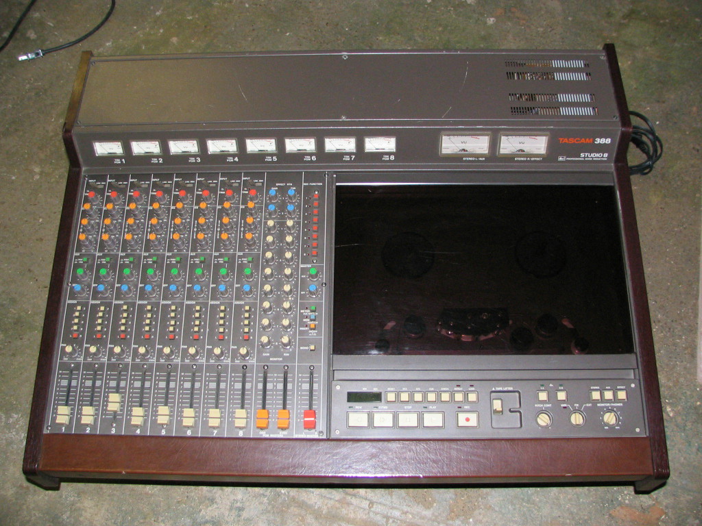
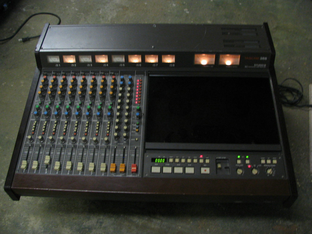
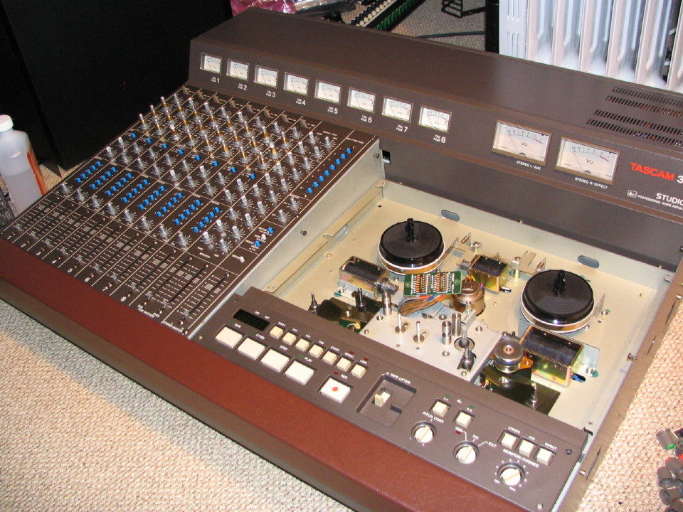
So I dug into the parts 388 and now all the meters look good.
  • did some further disassembly of the transport to clean and inspect

This thing is neat-neat-neat. The connections on each PCB type are unique from each other either in number of conductors or plug color so basically if you pull a PCB out you can't put the connectors back on wrong if you just match the number of pins and/or the color. It is a super easy system to work on. Somebody was thinking when they designed it and again I continue to be impressed with the build quality and engineering in a world progressively becoming more plastic and disposable...the 388 transport is very nicely outfitted and designed for handling 1/4" tape on 7" reels IMHO based on other systems I've worked on.
 
More progress...

Tonight I:

* got the wrist rest installed
* got the bottom panel back on
* reinstalled the TR PCB and that big heatsink on the back
* reinstalled the Capstan Servo PCB
* did some touch-up painting on the back panel
plugged in the Power Supply PCB and Reel Servo PCB and fired it up...

So far so good. All the meters light up, transport functions work great...no smoke. Yay. I didn't kill it.

Its looking really good...shiny. I focus so hard on the little tiny marks you can't see from a distance anyway but I know they're there...but when it all starts coming together those little marks get lost in all the shiny.
 
I focus so hard on the little tiny marks you can't see from a distance anyway but I know they're there...but when it all starts coming together those little marks get lost in all the shiny.

Same here, my friend, same here.:D;)

I can't wait for your 388 to be all done and ready! It's looking so nice. I bet the ease of servicing is light years ahead of something like a cassette portastudio.:D Looks like there is a lot of room to maneuver in there.:)
 
Back
Top